

Introduction: Arduino EL Wire Controller (sound Activated)

Parts list:
- Arduino Pro Mini 328 3.3V/8MHz (Sparkfun)
- 2 batteries Lipo 3.7v 150mAh, Lipo 3.7v 1200mAh (Adafruit)
- USB/DC Lipo charger 5-12V (Adafruit)
- inline power wire connector male (Adafruit)
- High brightness white el wire 2.5 m (Adafruit)
- EL inverter 3v (Sparkfun)
- JST right-angle connectors, through-hole 2-pin (Sparkfun)
- 4pin connector (male and female) from old CD drive
- breakaway 0.1" 36-pin strip male header (Adafruit)
- DPDT, SPTT switches scrounged from dead gear
- 4n28 optoisolator
- 2N6071 triac (Silicon Bidirectional Thyristor)
- resistors (2) 470 ohm, (1) 330 ohm, (1) 1k ohm all 1/4W
- push button and scrounged insulated wire (from audio cable 28 awg)
- misc screws and nuts, Altoids-like tin
Step 1: Circuit

This circuit isolates the el-wire stage from the Arduino using the optoisolator. Starting with the el wire stage, the signal from the optoisolator is used to drive the triac gate which acts like a switch for the HVAC coming from the inverter. Pins 1 and 2 of JP6_INVERTER connect the DC side of the inverter to the larger (1200mAh) battery. Note that the pin 3 of JP6_INVERTER also connects to the NEG side of this battery. As explained in quasiben's instructable, all you need to excite the phosphorous on the el-wire is one of the two wires to be connected to an oscillating voltage (pin 4 of JP6_INVERTER tied to JP1 pin 1). The pin 2 of JP1 then is connected to MT2 of the triac which is connected to ground whenever the triac's gate is set HIGH with the optoisolator signal (ultimately coming from the digital pin 5 from the Arduino microcontroller). It is important to keep this stage isolated from the sensitive circuit of the Arduino because of the high voltage coming out of the inverter and noise emitted from the high frequency generated by the inverter.
The Arduino stage has an audio sensor (mic) that is connected to JP5_MIC and analogue input pin A0 on the microcontroller. To set the volume level at which the digital pin out 5 is set HIGH, I used an ON OFF ON switch with two digital input pins (3 and 4). This lets me set three levels of audio cutoff, by first checking if pin 3 is LOW (if Y then MED_AUDIO) otherwise if pin 4 is LOW (HIGH_AUDIO, least sensitive) otherwise use LOW_AUDIO (most sensitive). Finally, the microcontroller will cycle through a menu system by detecting S1 momentary button presses using an interrupt associated with digital pin 2.
Step 2: Arduino Code
int triacGatePin = 5;  // drive el inverter thru optoisolator controlling triac
int monitorPin = 0; //from microphone

//for audio processing
int digInputA = 3; //pins to check for audio switch position
int digInputB = 4; //pins to check for audio switch position
int cutOff[] = {70, 110, 260}; //value to compare peaktopeak with
const int sampleWindow = 50; // Sample window width in mS (50 mS = 20Hz)
unsigned int sample;
unsigned int signalMax, peakToPeak = 0;
unsigned int signalMin = 1024;

int menuState = 0;  // variable to be updated by the interrupt
int pbPress = 0;
int triacState = LOW;
long previousMillis = 0;
long flashInterval = 0;
//variables to keep track of the timing of recent interrupts
volatile unsigned long button_time = 0;
volatile unsigned long last_button_time = 0;

void setup() {
  pinMode(triacGatePin, OUTPUT);
  pinMode(digInputA, INPUT);
  pinMode(digInputB, INPUT);
  //enable interrupt 0 (pin 2) which is connected to a button
  //jump to the increment function on falling edge
  attachInterrupt(0, increment, FALLING); //turn on interrupt for pin 2
}

void loop() {
  if (pbPress == 1){
    pbPress = 0;
    switch (menuState){
      case 0: //off
        while(pbPress == 0){
          //wait for next pbPress
          delay(10);
        }
        break;
      case 1: //audio
        while(pbPress == 0){
          int audioLevel = getSwitchState();
          // collect data for 50 mS
          unsigned long startMillis= millis();  // Start of sample window
          while (millis() - startMillis < sampleWindow)
          {
            sample = analogRead(monitorPin);
            if (sample < 1024)  // toss out spurious readings
            {
               if (sample > signalMax)
               {
                  signalMax = sample;  // save just the max levels
               }
               else if (sample < signalMin)
               {
                  signalMin = sample;  // save just the min levels
               }
            }
          }
          peakToPeak = signalMax - signalMin;  // max - min = peak-peak amplitude
          if (peakToPeak > cutOff[audioLevel]){
          //turn on led
          digitalWrite(triacGatePin, HIGH);
          }else{
          digitalWrite(triacGatePin, LOW);
          }
          resetValues();
        }
        break;
      case 2: //switch fast bink
        flashInterval = 120;
        while(pbPress == 0){
          unsigned long currentMillis = millis();

          if(currentMillis - previousMillis > flashInterval) {
            // save the last time you blinked the LED
            previousMillis = currentMillis;

            // if the LED is off turn it on and vice-versa:
            if (triacState == LOW){
              triacState = HIGH;
            }else{
              triacState = LOW;
            }
            // set the LED with the triacState of the variable:
            digitalWrite(triacGatePin, triacState);
          }
        }
        break;
      case 3: //switch slow blink
        flashInterval = 700;
        while(pbPress == 0){
          unsigned long currentMillis = millis();

          if(currentMillis - previousMillis > flashInterval) {
            // save the last time you blinked the LED
            previousMillis = currentMillis;

            // if the LED is off turn it on and vice-versa:
            if (triacState == LOW){
              triacState = HIGH;
            }else{
              triacState = LOW;
            }
            // set the LED with the triacState of the variable:
            digitalWrite(triacGatePin, triacState);
          }
        }
        break;
      case 4: //switch on
        triacState = HIGH;
        digitalWrite(triacGatePin, triacState);
        while(pbPress == 0){
          //wait for pbPress
          delay(10);
        }
        triacState = LOW;
        digitalWrite(triacGatePin, triacState);
        break;
    }
  }
  delay(100);
}

// Interrupt service routine for interrupt 0
void increment() {
  button_time = millis();
  //check to see if increment() was called in the last 250 milliseconds
  if (button_time - last_button_time > 250)
  {
    pbPress = 1;
    if (menuState == 4){
      menuState = 0;
    }else{
      menuState += 1;
    }
    last_button_time = button_time;
  }
}
//for audio processing
void resetValues(){
  signalMax = 0;
  signalMin = 1024;
  peakToPeak = 0;
}
int getSwitchState(){
  int pin2 = digitalRead(digInputA);
  int pin3 = digitalRead(digInputB);
  if (pin2 == 0){
    return 1; //Medium volume
  }
  if(pin3 == 0){
      return 2; //High volume;
  }else{
      return 0; //Low volume;
  }
}
Step 3: Project Enclosure
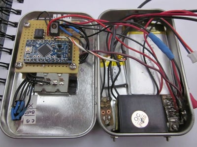

I kludged this thing into a Altoids tin size box and almost got it all in there. The Arduino pro mini and circuit components were soldered on to donut perfboard which was held above the lid's metal surface with standoffs. The inverter was attached to the bottom and the two batteries just fit (actually had to make a small hole where the bottom of the tin curves to allow the more angular, rectangular edge of the larger (el wire) battery to fit. I wanted to leave the headers on the pro mini board so that I can change code and add features if needed. To make sure the FTDI pins, which stick straight up from the board (and when the tin was closed, straight down to the bottom of the tin where the batteries are placed), didn't puncture the Lipo battery, I cut them a bit shorter but still long enough to allow the FTDI basic from Sparkfun to make good connections. Initially, I had the momentary switch that is used for menu selection adjacent to the inverter. This was a mistake because the emf coming from the el stage of the circuit triggered the menu to advance when there were rapid on/off cycles of the el wire (when on audio mode or Fast Flash). Tried several ways to correct for this (internal pullup resister, keeping wires short as possible, etc) and finally used my shielded cable from an audio plug going straight out of the tin with the switch at the end. I would redesign this entirely to maintain distance and possible shielding between the two stages.
I also passed two wires out that connected to ground of each battery and use these along with the positive connection to the mic and a second positive connection in the last position of JP5_MIC (which is really a 4 wire connector, 3 for the mic and the extra to the el battery pos). This way, I can charge the batteries without opening the enclosure.
Step 4: Attaching El Wire to Garment


I have gotten 3 hrs on audio flashing el wire pretty continuously and the batteries had more life.
Improvements:
- add rotary encoder to change audio level (instead of 3, could have 10 levels)
- filter audio with low pass and high pass filters to select between different sound types (pitch, etc)
- add additional optoisolators (w/ separate digital pin outs from Arduino) to control multiple el wire strands
- photo resistor to drive el wire when light level drops
Now, if only I could dance like these two robot dancers!
Thanks to those who have helped (mentioned at the beginning of this instructable).


![Tim's Mechanical Spider Leg [LU9685-20CU]](https://content.instructables.com/FFB/5R4I/LVKZ6G6R/FFB5R4ILVKZ6G6R.png?auto=webp&crop=1.2%3A1&frame=1&width=306)


