

Introduction: Arduino FTDI Header


So, you want to program a bootloaded AVR. Or possibly, you have an Arduino Lilypad and no way to program it. There are a few solutions available to you: You could buy a USB to FTDI adapter (available at Adafruit, Sparkfun, etc), you could buy a simple FTDI cable, or you could build something. I couldn't afford the "FTDI Friend," so, I decided to build an adapter to use the TX/RX Serial connection from the Arduino. It plugs in to the RX, TX, Reset, 5V, and GND pins on the Arduino and has a 6 pin female header for the FTDI connection. This can most likely be made with electronics supplies you already have.
Step 1: Materials
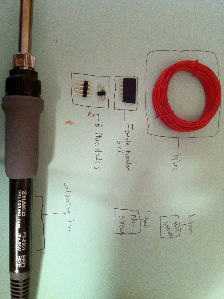
Not much is needed at all for this. The only materials you need are:
-5 Wires
-6 Pin Female Header
-6 Male Header Pins, broken into sections of 4 and 2
-Solder
-Electrical Tape
And the only tools you need are:
-Soldering Iron
-Wire cutters
-Hemostats help a lot with holding the wire in place
-Fine Tip Permanent Marker
Step 2: Soldering: Part I

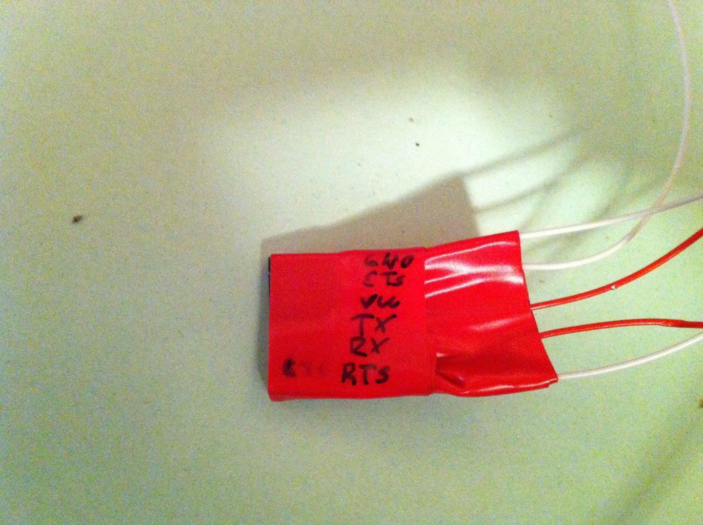
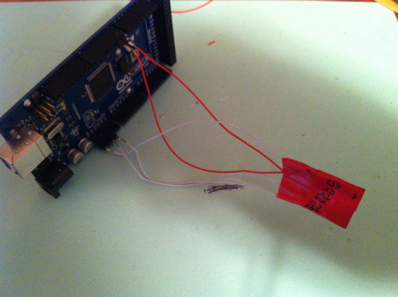
Solder your 5 cables to the header. I used red cables for the data and white for everything else. On the leftmost (or rightmost if you're turned the other way) side, connect the ground wire to both of the terminals on the end. Once you're done, wrap in electric tape and label it with the marker. Make sure to keep the cables aligned.
Step 3: Soldering: Part II
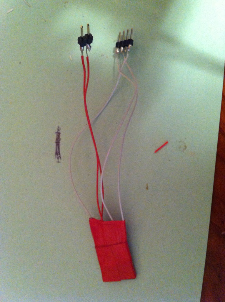

Now it's time to solder the other side. On the leftmost pin of the 4 pin male header (the one that was broken off of the 6 pin header) connect the RTS wire. This will be the reset pin on the Arduino. Skip the second-leftmost terminal and solder the third pin to VCC. Solder the rightmost pin to the wire for GND/CTS.
>
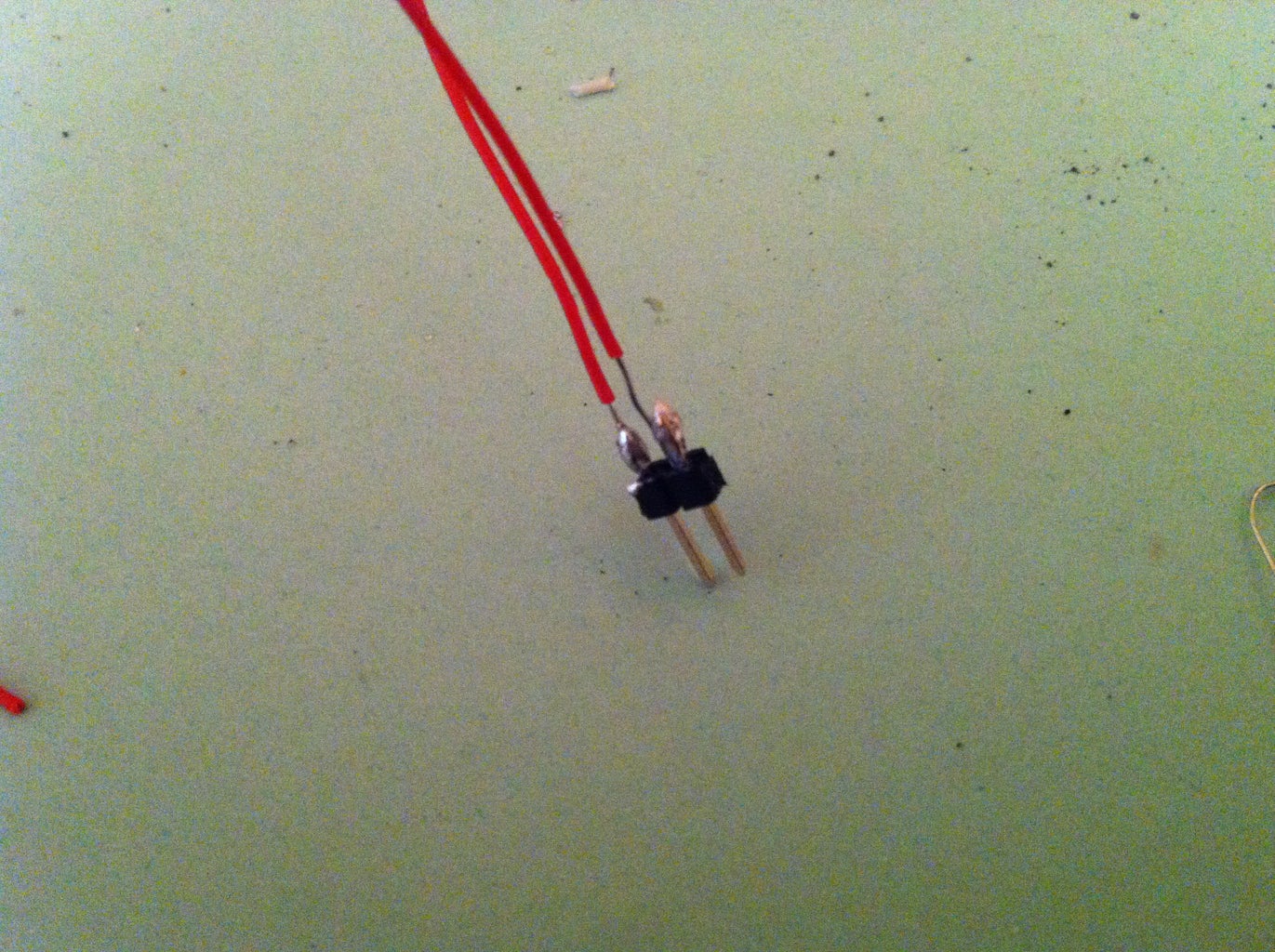
On the 2 pin header (the other part of the 4 pin), solder the left pin to TX and the right pin to RX.
Once complete, the pins will be laid out like so:
FTDI Header Pin = Arduino Pin
GND = GND
CTS = GND
VCC = 5V
TX = TX
RX = RX
RTS = Reset
On the 2 Pin header, you may want to label which is the TX and which is the RX (I learned the hard way)
Step 4: Finish Line
You are ready to connect! Plug in your 4 pin header into the bottom-left row of pins on the Arduino. Next, connect the TX/RX pins to 0/1 respectively. On the other side, connect your FTDI header to your device. To upload something, just upload as you usually would to your Arduino, but select your target board instead of the Arduino you are using. Note that this will also program your Arduino with your sketch. If you are using it for a Serial connection, just plug it in to your computer and communicate with it through your Arduino COM port. This method should work with both Arduinos using the FTDI Chip (Duemilanove and below) and with the ATmega8/16U2 (Uno and Mega2560). If ever it doesn't work, try flipping the TX/RX pins plugged into your Arduino. The FTDI header you just created uses the same pin layout as the FTDI Friend and the FTDI-USB adapter from Sparkfun.
Thank you for reading


