

Introduction: Arduino Footswitch (control Your Guitar Amp With Arduino)


This is my first project in this community and in the arduino platform, and now it just got featured in the Arduino official website. Thank you all for your support!!
So, you play music live, and you use metronome or click-tracks to synchronize your band. What if I told you that you can use that click-track to tell your amp to switch between channel by itself, in the exact time you need it, without you actually stomping on the footswitch?
If you are like me, you try to put up the best show you can. But it's not as easy as it looks. You have to pay attention to a lot of things while playing; avoid mistakes in your playing/singing, remember the changes of the song, move around the stage, interact with the crowd, etc. I’m not a trained musician, and though for most people all of this challenges can be overcome with practice and a lot of preparation; for me can be a bit overwhelming at times.
So I started to work in this idea, to have at least one little detail less to worry while playing live. I switch a lot between clean and distortion mid song, and now I feel a lot more free to play guitar and sing while the arduino changes channels for me.
But more important than that, I want to expand this idea and in the future automatically control not only the amp footswitch, but also mine and other bandmates equipment, lights, live projections, etc.
DISCLAIMER
Im self taught in electronics, and this was also my first arduino project. So you might find that a lot of this project could be have done a lot better, specially the code. Also, im from Chile (south america) my native tongue is spanish, not english. So please, be patient if my english is rubbish at times.
Step 1: The Concept

So, the way this thing works is by adding to the click track a sound or tone noticeable larger than the average clicks on it, whenever a change of channel is needed in the song. The arduino then detects this, and uses a relay to simulate the footswitch of the amplifier, effectively changing the channel.
This means that we need to build a relay system to plug in the amplifier (on the footswitch input), or in other words, replicate a footswitch but relay activated. This is not as difficult as it may sound. A footswitch is a fairly simple circuit to build, some of them are basically an interrupter that connects or disconnect a cable. The one i built has worked on at least 3 different brands of guitar amplifiers.
Also, it's a good idea to add an audio amplifier to amplify the signal from the click-track to make sure the arduino is going to detect the instructional beep properly.
Step 2: Materials


- 1x Arduino
- 1x LED
- 1x resistor, any value up to 1K ohm (for the led)
- 1x 10k resistor
- 3x 100K resistor
- 1x 47nF
- 1x 10uF
- 2x 0.1uF capacitor
- 1x 2n3904 or any NPN transistor (2n5088, 2n2222, etc.)
- 1x jack audio 1/4
- 1x jack audio 35mm (or another jack 1/4 instead, in case you're going to send the click-track from an audio interface)
- 1x 5V relay, or a relay module
- 1x DPDT Switch momentary (in case you need to manually change the channel, you will still be able to)
- 1x enclosure of some kind
Step 3: The Relay Footswitch

First, we need to know what footswitch we are going to replicate. For this, just simply google the model of your footswitch with the words "wiring diagram" or the name of your amp with the words "footswitch wiring". Trust me, you'll find it eventually.
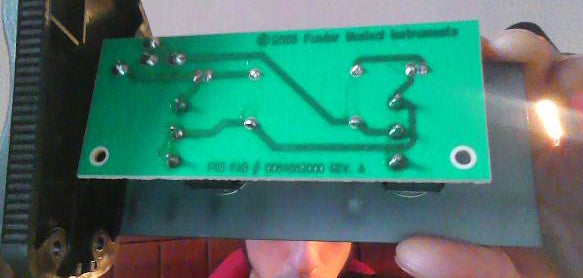
Or you can also do what i did, just open the footswitch, take a picture of the pcb board and re-draw the diagram.
In my case, I replicate the footswitch of my Fender Champion 100. But, as i said before, I tried it on a Roland Cube and on an Orange head and it worked all right on both.
Once you have the circuit replicated, just put the relay in the exact place where the switch would go. And that’s it, first step done. We will control that relay (and the guitar amp) through the arduino later.
You could even replace the switch on your original footswitch with a relay. I didn’t do that on mine, cause i was afraid to start experimenting on it.
Step 4: The Signal Amplifier


As i said earlier, its a good idea to amplify the click-track signal we are going to feed onto the arduino. For this, I used a circuit that I found in this link (image-1).
This little audio amplifier will get his power from the 5volts output of the arduino.
Also, not only we need to amplify the signal, we should also modify it a little. This is highly recommended so we can use the most of it.
This is an idea that I took from instructables member amandaghassaei in the step 4 of her instructable: Arduino-Audio-Input.
Basically, because an audio signal oscillates between negative and positive values, and arduino works only with DC positive current; we can only use the positive part of the audio signal, losing half of the audio "information". (image-2)
So, in order to use the full audio wave, we add a dc voltage offset to the signal. This way, although the signal keeps oscillating, all of its values keep being positives. (image-2)
We can do this by adding the circuit in image-3 after the amplifier circuit we just use.
The 5volts will come directly from the arduino and will get converted into 2,5volts through the resistors and will be added to the audio signal. Now the signal oscillates around 2,5volts and all in positives values that the arduino can read.
Step 5: The Wiring

Now, we can start connecting the elements we have: The relay footswitch, the signal amplifier, and the arduino.
Here I added the momentary switch connected to pin 10 to activate the relay-footswitch manually, in case we need it.
This is optional, but I also connected a led to pin 8 of the arduino, to notify if clicks or sounds are being detected.
Step 6: The Arduino Code
Almost done, we only have write the code. I want to remind you at this point that this is my first arduino code, it took me weeks to write it and make it work, and I know that it still could be a lot better. Anyway, please be patient because it may get a little messy here.
The way the code work is that in every loop, the arduino checks if it is detecting any sound from the audio input in analog pin A1. Sound is defined here as any value below or above the 300 to 720 range. This is because the signal now oscillates between 2,5volts which is 512 when analog read. So the values in the 300 – 720 will be most likely noise, hum, and silence (you can tweak this values in the code if you want to).
Now, if the arduino detects a sound, it will start counting every sound and silence in the following loop cycles. If the total count of sounds and silences together gets to 500, with the majority of them being sounds, the arduino interpret this as one of the instructional-tones we will add on our track, and then will activate the relay to change the amp channel. If the silences turn out to be majority, the arduino will interpret that the sound was just another click on the click-track and subsequently ignore it, reset the count, and start again.
int audioInput = A1;                //audio clicktrack
const int ledSound = 8;             //Led that indicate if sound is detected
const int relayPin = 9;             //pin connected to relay
const int switchControl = 10;       //momentary switch for manual change of channel

//define Sound detection variables
int soundValue = 0;                   //value of the sound detected by the audio input (0 - 1023)
int counterSound = 0;                 //how much sound has been detected
unsigned long counterSilence = 0;     //how much silence has been detected
unsigned long timeSoundStarted = 0;   //time when sound/tone started in milliseconds
unsigned long timeSound = 0;          //amount of time the sound/tone lasted in milliseconds

//define Switch detection variables
unsigned long tiempoSwitchStart = 0;    //time when switch started being pressed
unsigned long tiempoSwitchPressed = 0;  //amount of time the switch remained pressed
unsigned long currentMillis;            //current time in milliseconds
boolean switchOpen;                     //state of the switch (pullUp button, "true" when open or NOT engaged, and "false" when pressed)
int switchPreviousState = 0;            //Previous state of the switch 0=not pressed / 1=pressed

//define Relay state variable
boolean relayEngaged;


void setup() {
  // setup code - run once:
  pinMode(audioInput, INPUT);  //setup Relay
  pinMode(relayPin, OUTPUT);
  digitalWrite(relayPin, LOW); //start with relay disengaged

  //setup LEDs
  pinMode(ledSound, OUTPUT);  //setup Switch
  pinMode(switchControl, INPUT_PULLUP); //reads LOW when pressed
}

void loop() {
currentMillis = millis();                   //read current time
soundValue = analogRead(audioInput);        //read sound value from the audio input
switchOpen = digitalRead(switchControl);    //read switch state

// SWITCH FUNCTIONS
if (switchOpen == false && switchPreviousState == 0) {  //if the switch is being pressed and its previous state was not pressed
  switchPreviousState = 1;                              //define the switch state as active (this will be the previous state next time)
  tiempoSwitchStart = millis();                         //define the exact moment the switch was pressed
  delay(10);
}

else if (switchOpen == true && switchPreviousState == 1) {  //if the switch is released (NOT pressed) and its previous state was pressed
  switchPreviousState = 0;                                  //define the switch state as inactive (this will be the previous state next time)
  tiempoSwitchPressed = millis() - tiempoSwitchStart;       //define how much time the switch remained pressed
  relayEngaged = digitalRead(relayPin);                     //read relay state if (relayEngaged == false && tiempoSwitchPressed >= 10) { //if the relay is NOT engaged
    digitalWrite(relayPin, HIGH);   //engage the relay
    delay(10);
    //if your footswitch uses a momentary type switch add the following code:
    //digitalWrite(relayPin, LOW);
    //if not, ignore this comment
  }

else if (relayEngaged == true && tiempoSwitchPressed >= 10) { //if the relay IS engaged
    digitalWrite(relayPin, LOW);      //disengage the relay
    delay(10);
    //if your footswitch uses a momentary type switch add the following code:
    //digitalWrite(relayPin, HIGH);
    //if not, ignore this comment
  }
  counterSilence = 0;
  counterSound = 0;
}


// DETECT SOUNDS
if (soundValue <= 300 || soundValue >= 720) {   //detect if the sound value exceed the values between 300-700, which are most likely hum, noise and silence
  if (counterSound == 0) {                      //if sound is detected for the first time...
    timeSoundStarted = currentMillis;           //remember the moment in milliseconds
  }
  digitalWrite(ledSound, HIGH);                 //turn on the sound detection led
  counterSound ++;                              //count +1 sound
}
else if (soundValue > 300 || soundValue < 720) { //detect if the sound value DOESN´T exceed the values between 300-700 (silence)
  digitalWrite(ledSound, LOW);                   //turn off the sound detection led
  if (counterSound > 0) {                        //if sound hasn't been detected before, dont count this silence
    counterSilence ++;                           //count +1 silence
  }
}
else {
  digitalWrite(ledSound, LOW);
}

// ENGAGE THE RELAY
if (counterSound > 0) {                         //if sound has been detected
timeSound = currentMillis - timeSoundStarted;   //define how much sound and silence has been counted since the sound started
relayEngaged = digitalRead(relayPin);           //read relay state

  //if more silence was counted in 50 milliseconds, just return everything back to 0
  if (timeSound >= 50 && counterSilence > counterSound) {
    counterSilence = 0;
    counterSound = 0;
    timeSound = 0;
  }

  //if more sound was counted during 500 milliseconds and the relay is NOT engaged, engage the relay
  else if (timeSound >= 500 && counterSilence < counterSound && relayEngaged == false) {
    digitalWrite(relayPin, HIGH);
    //Again, if your footswitch uses a momentary type switch, add the following code:
    //delay(10);
    //digitalWrite(relayPin, LOW);
    //if your footswitch is not momentary, ignore this whole comment
    delay(750);
    counterSilence = 0;
    counterSound = 0;
  }

  //if more sound was counted during 500 milliseconds and the relay IS engaged, disengage the relay
  else if (timeSound >= 500 && counterSilence < counterSound && relayEngaged == true) {
    digitalWrite(relayPin, LOW);
    delay(750);
    counterSilence = 0;
    counterSound = 0;
  }
}

}
If everything done well, when plugging the click-track signal to analogpin A1, the LED should be lighting at the same time the click sounds.
To test if the relay system is working, we could send any sound louder and longer than the clicks, and see if the relay engages. I used the tone generator in this link.
Or you could just start making the click-tracks with the instructional tones, as I explain in the following step.
Step 7: Prepare the Click-track


As we said before, in order to tell the arduino when to activate the relay and change channels, we need to send it a beep, tone, or sound a few millisecond longer than the clicks.
The code I write needs this tone to lasts at least 500 milliseconds. So lets add this instructional-tone to our click-track.
There are several ways to do this, anything will work as long as the sound is clear, constant and lasts what it need to lasts. I will show you how I did it on Audacity.
First we add the click-track and our original song with all the instruments, making sure that both track are in sync. This is very important because we'll use the original song as a guide to know when to add the channel-switching-tone to the click-track.
Play the song and when you identify those moments when a channel switch is needed; stop the song. In the click-track (or in a new track) select a space of time similar to 500 milliseconds or more, and go to menu Generate > Tone.
Choose the following options:
wave = Square, no alias
frequency = 330
amplitude = 0,5
I found that those settings works the best.
Repeat this process in every part of the song it is needed. Make sure you place these tones so they finish right in the moment where you need the switching. This is because the arduino will first read the tone and when it is finished it will then switch the relay-footswitch So your change of channel will always be when your tone ended.
Now just delete the original song, and export this new click-track with the switching-tones added. Plug it to our system and it should work.
Step 8: The Enclosure


In this part you're free to use your own creativity. I design a board-like enclosure, with the idea of put things on top of it, like a pedal-tuner and a power supply. But any type of enclosure will work.
Anyway, here are some pictures of mine. Im proud of it because a lot of parts on it comes from stuff i found in the trash. Even the plastic leather (i took it from a destroyed leather sofa).
Step 9: Done! - How to Use It
Yep, thats all. I know it might be a complicated project, and i hope i've explained well enough, I did my best. But if this was my first time arduino project and somehow i managed to make it work, i'm sure you will too.
Now...
- plug your computer/audioInterface/mp3player on the click-track input
- plug your guitar into your amp
- plug a ¼ cable from our footswitch output to the footswitch input of your amp
- play the click-track on your computer/audioInterface/mp3player
- check the led is lighting at the same time that the clicks
- start rocking! ...your channels will know when to change themselves.
Step 10: Possible Modifications


There are some things I did add to this project, that i didnt mention here because are optional (and because its not easy for me to write in english). But I'll mention them now, in case you want to try them yourself and you need me to write an explanation on how to do them.
- Add a Left-or-Right Switch, in case you have a click-track stereo (with click on one side and music/FXs on the other) I put a switch to choose which one of the sides (left or right) you want to send to the arduino.
- Add an output with a copy of the click-track audio so you can plug in-ear monitors headphones for you, or other bandmate. I wired a cable from the output of the signal amplifier we made earlier to the input of an audio amplifier module PAM8403, to plug my headphones into it, and control its gain independently of the rest of the circuit.
- Extend the concept to Multi-effects pedals. This could simply be extended to some kind of Multi- effects pedals. A lot of them switch effects with only tact-switches buttons (as you can see in this link) that could easily be replaced with relays, and then controlled with an arduino.

Participated in the
Arduino Contest 2016

Participated in the
First Time Authors Contest 2016


