

Introduction: Arduino Grove WiFi Enabled Greenhouse


The Essentials:
Grove
- Grove- High Accuracy Temperature/Humidity Sensor
- Grove- Analog Light Sensor
- Grove- Encoder
- Grove- UV Sensor
- Grove- Soil Moisture
- Grove- RGB 16x2 Display
- Grove- 20CM Cable x3
- Grove- 50CM Cable x2
- Grove- Sensor Shield (Buy the one meant for UNO NOT MEGA)
Alternative: Grove Indoor Environment Kit for Edison if you're budget conscience
Controllers and Shields
- Arduino Mega
- Arduino WiFI Shield (not necessary for function)
- Remote Controlled Relays
- WiFI Controlled Relays (optional)
- IR Controlled Relays (if budget conscience)
Peripherals
- 12V CPU Fan (Optional)
- 12V Water Pump (Optional and coming soon to my project)
- 12V LED Grow Lights (Optional)
- Stand Offs (M2 and M3)
- Terminal Block (optional)
- ON/OFF Switch or Momentary Reset Switch (optional)
- 12V Connectors for Power Daisy Chains (optional)
- Greenhouse
Tools
- Drill
- Stepper Bits + Normal Bit Set
- Screw Drivers
- Wire Strippers
- Dykes
- Screws/Nuts for Mounting
The Bluno is a great way of transferring data through its apps of sensor readings. Its not too expensive and provides much more utility than a normal Mega. The only reason I am not using it is because the need of a mountable case.
The WiFi controlled relay makes this an IoT project and it works great. The only downfall of the relay is that it requires a LAN cable hook up. There are now true WiFi relays on the market but I haven't gotten the opportunity to use one yet. If you chose this option you will need a LM7805 however they heat up rather quickly so you either want a Murata 5v regulator or a large heatsink for the 7805 or perhaps they have a 12V flavor now. I have a video of the WiFi relays in use but for now Im going for the much cheaper IR Relays.
Step 1: Placement


Remove the adhesive backing of the LED strip and lay it out around the top perimeter. Drill of the greenhouse making sure the power connector is near where you want the terminal block/power distribution point to be.
Next you will want to place out the sensors and components on the greenhouse to your liking. Just lay the greenhouse on its side and populate it. Something to consider is that you have 2x 50CM cables which I like to reserve for the soil moisture and the temperature/humidity sensor since you would want it placed away from the ventilation fan. Make sure you have adequate slack for all sensors.
Once everything is placed you can mark the holes with a fine tip sharpie or hold onto the sensor and drill through the mounting holes. Either method you go with you will want to drill out the mounting holes on the sensors ever so slightly. I included a picture of how finely I drilled out the holes. The mounting holes run on the tight side making even .5MM off too tight to mount without bending the sensor board.You do not need to do it to all mounting holes, just enough so everything fits without bowing. Buy M2 stand offs and screws for these sensors while using M3 for the Arduino itself.
The 1/2" holes on the greenhouse walls are for routing the grove cables from the interior sensors to the exterior Arduino Mega. The holes can be any size but just make sure it is enough to get the connector head through and without nicking the wire when it is being pulled through the hole.
Lastly for the fan, I did not have much confidence in myself to dremel out a perfect circle for the air flow so I just made multiple 1/2" holes to accommodate the airflow and it works just fine. Not an overwhelming amount of wind, just a gentle breeze.
I may be leaving something out. Please PM or comment if you have ANY questions.
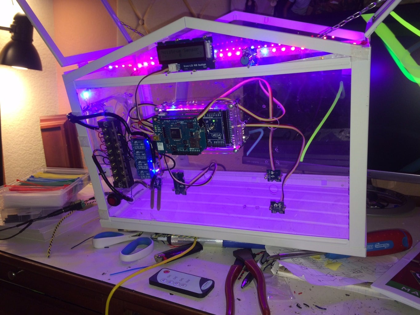
Step 2: Power Distribution


So to recap we have an Arduino, lights, a pump (in the future), four relays, and a ventilation fan all needing power. There are two schools of thought; just make it workor making it clean rather than a rats nest. So I opted for a terminal block and a push button switch ( had some problems with the switch I will talk about later).As a power supply I used a 3 amp 12 volt supply which is sufficient. The LEDs surprisingly draw a lot of power. After looking at how power hungry each item was I figured the minimum would be a three amp supply or even better a 4 amp supply. Even my 3 amp supply is getting warm during my burn in test. Probably a good 130 degrees Fahrenheit.
I also included a type of tape everyone needs. Its a fuzzy cloth electrical tape made by TESA that also serves as abrasion tape. I use it to wrap up wires I'm routing or for wires that will experience some nicking from use like these holes you route the wires through. Alternatively you can use spiral harness cable wrap you see me use on some photos.
I also began to mount the sensors just to see how it looked and in my opinion it looks great. The power distribution block is serving its purpose and is cleaning up the wiring. The only thing that looks messy at this point are the grove connectors.
I may be leaving something out. Please PM or comment if you have ANY questions.
Step 3: Extracting It From Its Paper Prison and Making Thought Reality


I like trying to make things tidy and visually appealing. So when you're at this stage, take a look at what you built and see if you can make it cleaner and more robust if it were to get tampered with. I used spiral harness cable wrap for extended lengths and and the short runs going to Bus to Relay and are all a conformal Z shape measured well and ziptied. The Grove sensors will always look a little messy unfortunately but they make projects so much easier.
I wired up the relays to be controlled by IR so the relay coil just goes to power and ground with no switch in between. The momentary switch I mentioned ended up being just an on/off but with power passing through the LED; it nerfed the voltage to 5v so nothing worked.The breadboard volt rails act as my screw terminal buss bar.
I may be leaving something out. Please PM or comment if you have ANY questions.
Step 4: The Code, See Next Step for Pro Tips
Here is the code in fully working order as an attachment. Make sure you follow instruction on next step.
Or use Codebender! For whatever reason I cannot put the code here in text since some elements are not allowed.
You will also want to install this Github Library, These libraries are important or else this does not work! To use, click "Download Zip". When you open up your Arduino IDE click SKETCH>IMPORT LIBRARY> ADD LIBRARY
It will ask you to find the zip file you just downloaded. Find it and click it. You now have the libraries needed for this to work!
If the link does not work search in Github this "Grove_Indoor_Environment_Arduino"
Attachments

Step 5: Code Tips to Get Working


First I'am using Arduino IDE V1.7.6 This is important if you have a new WiFI sheild, if you use a different IDE for your WiFi shield that works. Be my guest. (You also don't necessarily need WiFi)
In the code box you must find where you need to place your network name and password. I added it in CAPS where you need to look. It is towards the top. Here is what it says so you can do a CONTROL-F
"typedef int (*pgetSensorValue)(void);
rgb_lcd lcd;
boolean isBackLightOn = true;
char cmdstr[CMDSTR_MAX_LEN];
char ssid[48] = "ENTER YOUR NETWORK NAME HERE BETWEEN QUOTE MARKS"; // your network SSID (name) char psw[48] = "ENTER YOUR WIFI PASSWORD BETWEEN THE QUOTE MARKS"; // your network password"
Here are pin assignments you can alter if you so choose. The digital pin configuration does not refer to actual pins rather connector position you can see in the picture. As you can see this code allows for even more grove sensors which I opted not to choose like a button, servo, buzzer, relay, and PIR
"const int LightSensorIndex = 1;
const int UVSensorIndex = 2; const int THSensorIndex = 3; const int LocalIPIndex = 4;
const int pinSound = A0; const int pinMoistrue = A1; const int pinUV = A2; const int pinLight = A4; const int pinButton =5; const int pinEncoder1 = 2; const int pinEncoder2 = 3; const int pinBuzzer = 4; const int pinRelay = 8; const int pinPIR = 6; const int pinServo = 6;"
I used the default:
Temperature&Humidity SensorI2C
Moisture SensorA1Light
SensorA2UV
SensorA3PIR Motion
SensorD7EncoderD2ButtonUART(D1)
LCD RGB BacklightI2C
RelayD5
ServoD6
BuzzerD4
I may be leaving something out. Please PM or comment if you have ANY questions.
Step 6: The Final Product


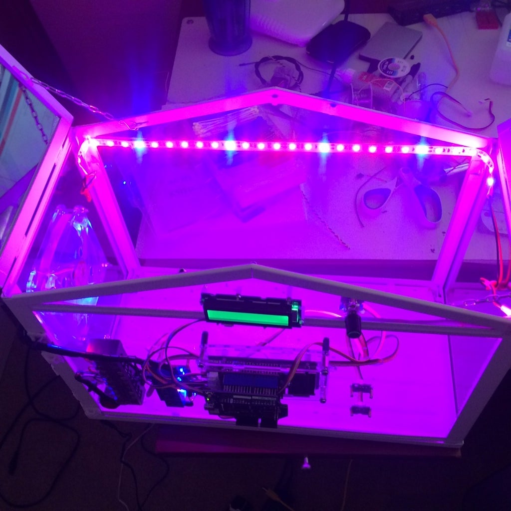


Using the relay remote control you can now activate LED strips, 12V Venting Fan, and the Arduino Sensors/WiFi.
The display will show you Moisture, Temperature and Humidity, UV Light, Visual Light, and the coolest thing of all the WiFi IP address so you may monitor elsewhere in the home. Just enter the IP address in an Internet Program URL and you may need to add a :1234 to define the port. This should work.
Check this Site Out if You Have Some Problems
It is the Edison's Garden Wiki which is actually pretty compatible with this Arduino conversion.
One recommendation is to use the WiFi shield above the Grove shield, it helps with transmission for some reason. If you choose grove on top, you will need a M/F SPI connector on the WiFi shield as it only has the female portion.
Check the video I made with WiFi relays!
Step 7: Trouble Shooting
I kind of already glossed over issues I had trying to fix. Here is what I can add...
- And Arduino Uno barely has enough memory for the code and it will display that it may not function properly. Hence the use of the Mega.
- Problems with placement, you could easily over drill your holes or find the stand offs you're using are too big. Keep in mind these require the small M2 stand offs. If you have little confidence about placement, try taping the sensors in place and use a string to measure the distance making sure you have a bit of slack in the thread.
- Once complete do a "Burn In Test", I am in EE test engineering and this is a crucial part of testing. If for what ever reason you are drawing more power than you expected you will find out rather quickly. Basically have EVERYTHING on and leave for 8 hours. Periodically check the heat of everything with heat potential. Does the power supply burn your hand? Are the relays for whatever reason warm to the touch? Are the LEDs melting the plastic? Once the test is over and thing seem okay, you have a safe unit.
- I was having issues with power and display flickering. I found it ended up being the SPI terminal. "When in doubt BEEP it out". Make sure each SPI lead has continuity with all shields.
- If you plug in power and nothing happens, take your meter and apply it to your negative and positive terminals on your greenhouse, you have a Short!
- The code is long, if you are using a long USB cable especially connected to a hub. You have a serious chance of corrupting data since at that length it is basically a small antenna. Shorten it up!
- "I want a water pump!" I do too!, I'm working on the idea, I do not want to over pour water at blasting speed. No, I plan on using an LM7805 or Murata Regulator and a 5V pump. With the last relay I have remaining I think applying it to a timing relay would be a good idea. Set the relay for two seconds and that should be sufficient. It is silly to have relays triggering relays but that's what I have come up with.
- "One of my sensors is not working D:" This can be solved a couple ways. Try swapping out the grove connector, if that doesnt work remove the sensor and look at physical damage. I had a sensor with a resistor missing, I googled it's schematic and found the value then I replaced it with a through hole resistor very carefully. You need Eagle to view files.
- "This is just one big cluster****" Not to worry! You do need a meter for this part but it is pretty simple. With the device unplugged you start with power input, check for shorts. If that's good move on to the next peripheral directly after power like the Bus bar. If each terminal has power check the next step down which would be the relays. See if you can manually proc them with a 9v battery and if you wired it up correctly. Next the arduino, check the obvious things like continuity with ground and Vin. Check the SPI pins. Check that all shields are in position by BEEPING out the lower pins with the top pins. Check the LEDs and Fan if they function with a 9v battery. Once you have done all of this your problem will be solved.
- Lastly check the code out. Maybe you are using I/Os that are not being used by the Arduino?
- For further assistance check HERE.
- Don't be afraid to post questions, I am eager and happy to help.


