

Introduction: Arduino Guitar Pedal


The Arduino Guitar Pedal is a digital multi-effect pedal based upon the Lo-Fi Arduino Guitar Pedal originally posted by Kyle McDonald. I made a few modifications to his original design. The most noticeable changes are the built-in preamp, and the active mixer stage which lets you combine the clean signal with the effects signal. I also added a sturdier case, foot switch, and rotary switch to have 6 discreet steps between the different effects.
The cool thing about this pedal is that it can be endlessly customized. If you don't like one of the effects, simply program another one. In this way, this pedal's potential is largely dependent upon your skills and imagination as a programmer.
Step 1: Go Get Stuff
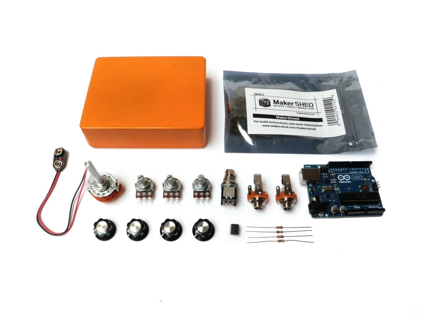
You will need:
(x1) Arduino Uno REV 3
(x1) Make MakerShield Prototyping Kit
(x3) 100K-Ohm Linear-Taper Potentiometer
(x1) 2-Pole, 6-Position Rotary Switch
(x4) Hexagonal Control Knob with Aluminum Insert
(x1) TL082/TL082CP Wide Dual JFET Input Op Amp (8-Pin DIP)
(x2) 1/4" Stereo Panel-Mount Audio Jack
(x4) 1uF capacitor *
(x2) 47uF capacitor *
(x1) 0.082µf Capacitor
(x1) 100pF Capacitor **
(x1) 5pf Capacitor **
(x6) 10K Ohm 1/4-Watt Resistor ***
(x2) 1M Ohm 1/4-Watt Resistor ***
(x1) 390K Ohm 1/4-Watt Resistor ***
(x1) 1.5K Ohm 1/4-Watt Resistor***
(x1) 510K Ohm 1/4-Watt Resistor ***
(x1) 330K Ohm 1/4-Watt Resistor***
(x1) 4.7K Ohm 1/4-Watt Resistor ***
(x1) 12K Ohm 1/4-Watt Resistor ***
(x1) 1.2K Ohm 1/4-Watt Resistor ***
(x1) 1K Ohm 1/4-Watt Resistor ***
(x2) 100K Ohm 1/4-Watt Resistor ***
(x1) 22K Ohm 1/4-Watt Resistor ***
(x1) 33K Ohm 1/4-Watt Resistor ***
(x1) 47K Ohm 1/4-Watt Resistor ***
(x1) 68K Ohm 1/4-Watt Resistor ***
(x1) Heavy-Duty 9V Snap Connectors
(x1) 90-Ft. UL-Recognized Hookup Wire
(x1) 9 Volt Battery
(x1) Box 'BB' Size Orange Powder Coat
(x1) DPDT Stomp switch
(x1) 1/8" x 6" x 6" rubber mat
(x1) 1/8" x 12" x 12" cork mat
* Electrolytic capacitor kit. Only one kit necessary for all labeled parts.
** Ceramic capacitor kit. Only one kit necessary for all labeled parts.
*** Carbon film resistor kit. Only kit necessary for all labeled parts.
Please note that some of the links on this page contain Amazon affiliate links. This does not change the price of any of the items for sale. However, I earn a small commission if you click on any of those links and buy anything. I reinvest this money into materials and tools for future projects. If you would like an alternate suggestion for a supplier of any of the parts, please let me know.
Step 2: Header Breakdown


Break the male header strip down to fit properly in the Maker Shield kit.
An easy way to do this is to insert the end of the strip into each of the Arduino sockets and then snap off the excess pins. You will end up with 4 strips of proper size.
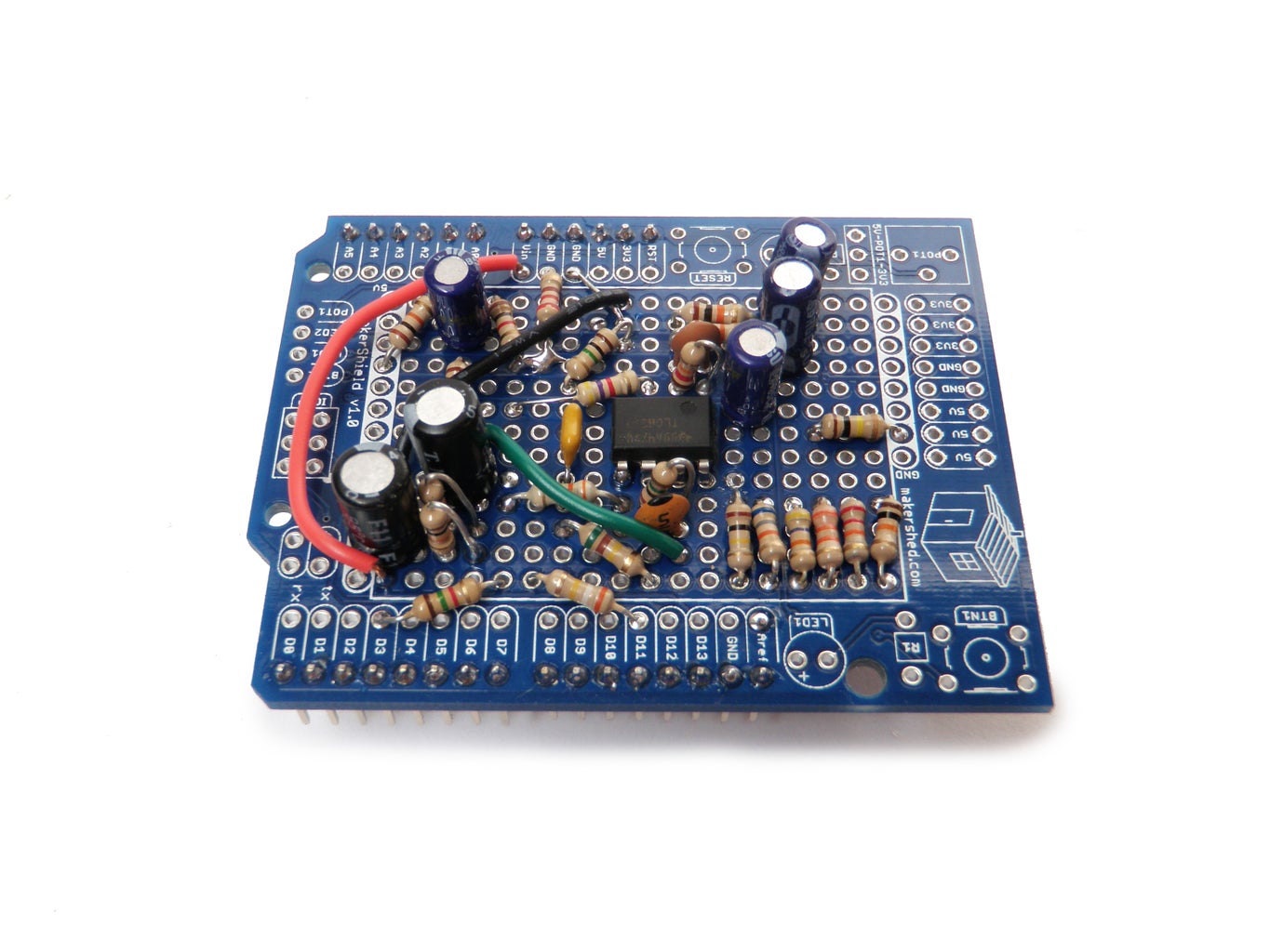
Step 3: Solder

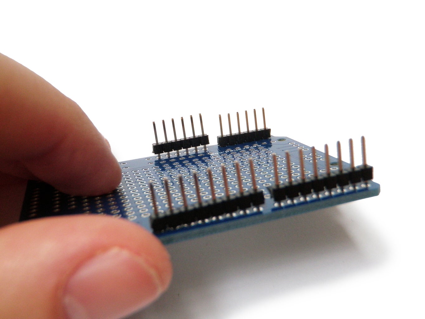

Insert the male header pins into the Maker Shield and solder them into place.
Step 4: Template


Print out the attached template on full-sheet adhesive paper.
Cut out each of the two squares.
(The file has the pattern repeated twice in case to optimize use of the paper, and in case you need an extra.)
Step 5: Drill


Peel off the backing of the adhesive template and stick it squarely on the front of the casing.
Drill all of the crosses with a 1/8" drill bit.
Starting from the left side, widen the first three holes with a 9/32" drill bit.
Widen the last hole of the top row with a 5/16" dill bit.
And then widen the singular hole in the bottom right with a 1/2" spade bit to finish off the front of the case.
Peel off the adhesive template from the front of the case.
Next, stick the next adhesive template to the back edge. In other words, stick it to the edge face most closely abutting the potentiometer holes.
Drill the crosses first with 1/8" holes and then widen them with larger 3/8" holes.
Peel away this template as well, and the case should be ready.
Step 6: Wire the Pots

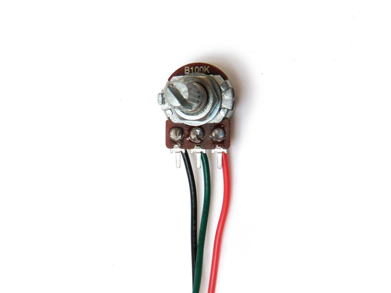
Attach three 6" wires to each of the potentiometers.
For simplicity's sake, you should attach a black ground wire to the pin on the left, a green signal wire to the pin in the middle, and a red power wire to the pin on the right.
Step 7: Wire the Rotary Switch

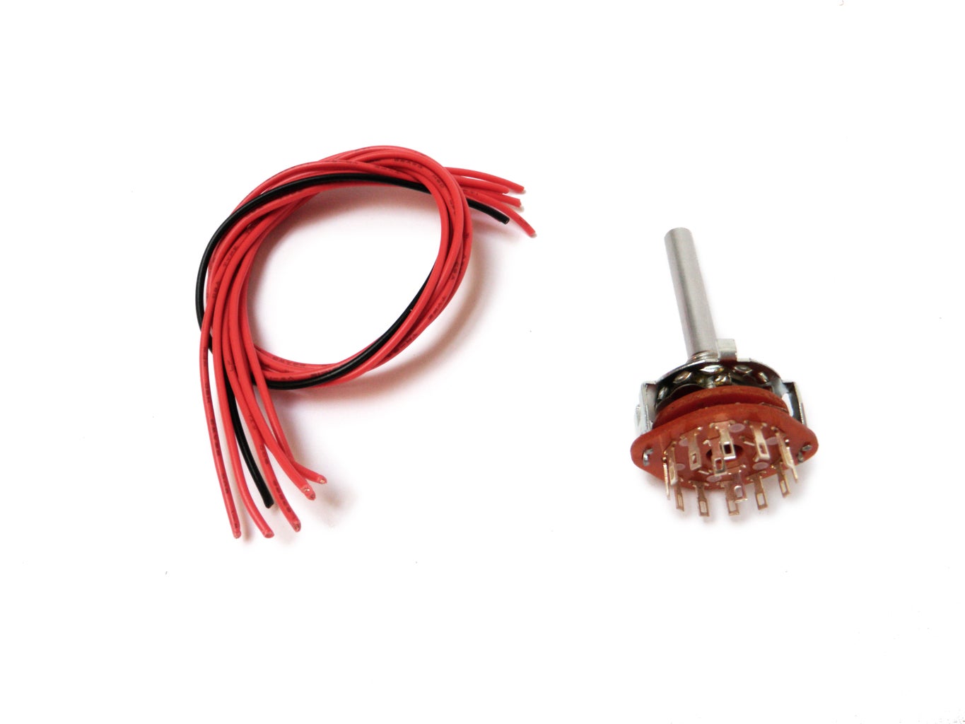

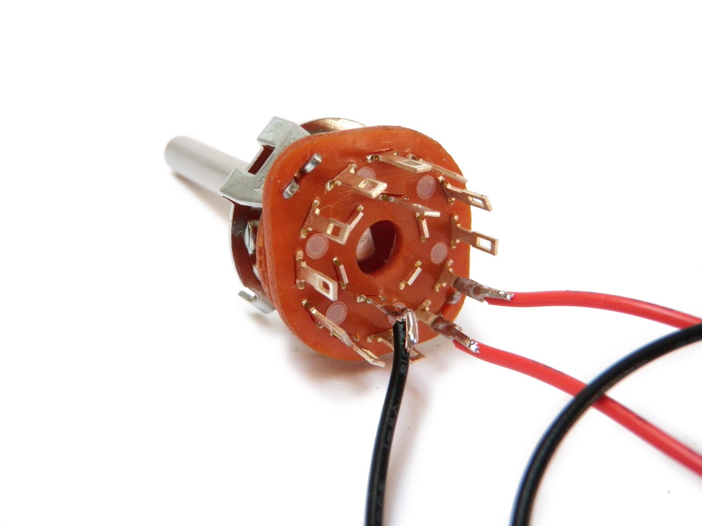
Attach a 6" black wire to one of the inner pins.
Next, attach 6" red wires to the 3 outer pins both to the immediate left and right of the black inner pin.
To be sure you did this right, you may consider testing the connections with a multimeter.
Step 8: Build the Circuit
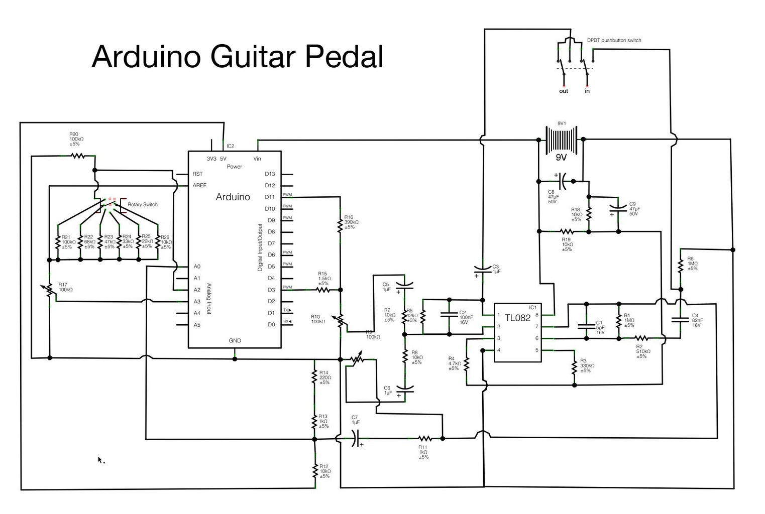
Start to build the circuit as pictured in the schematic. To see the schematic larger, click the little "i" in the upper right-hand corner of the image.
For now, while building the circuit, do not worry about the potentiometers, rotary switch, bypass switch, and input jacks.
To better understand what you are doing, this circuit consists of a few different parts:
Preamp
The preamp uses one of the two op amps packaged in the TL082. The preamp is both boosting the guitar signal to line level and inverting the signal. When it comes out of the op amp the signal is split between the Arduino input and the "clean" volume knob for the mixer.
Arduino Input
The input for the Arduino was copied from Kyle's input circuit. It is basically taking the audio signal from the guitar and constraining it to roughly 1.2V, because the aref voltage within the Arduino has been configured to look for an audio signal in this range. The signal is then being sent to analog pin 0 on the Arduino. From here, the Arduino is then converting this to a digital signal using its built in ADC. This is a processor intensive activity and where most of the Arduino's resources are being allocated.
You can get a faster conversion rate and do more multiprocessing of the audio signal using timer interrupts. To learn more about that, check out this page on Arduino Real-Time Audio Processing.
Arduino
The Arduino is where all of the fancy-shmancy digital signal processing is happening. I'll explain a bit more about the code later. For now, in relation to the hardware, what you need to know is that there is both a 100k potentiometer connected to analog pin 3 and a 6-position rotary switch connected to analog pin 2.
The 6-position rotary switch is functioning in a similar way to a potentiometer, but rather than sweeping through a resistance range, each pin has a discrete resistance associated with it. As you select different pins, voltage dividers of different values are created.
Since the analog reference voltage had to be remapped to handle the incoming audio signal, it is important to use aref as the voltage source, as opposed to the standard 5V for both the rotary switch and the potentiometer.
Arduino Output
The Arduino output is only loosely based on Kyle's circuit. The part I kept was the weighted pin approach to get the Arduino to output 10-bit audio using only 2 pins. I stuck with his suggested weighted resistor ratings of 1.5K as the 8-bit value and 390K as the added 2-bit value (which is basically 1.5K x 256). From there I scrapped the rest. His output stage components were unnecessary because the audio was not going to an output, but rather to the new audio mixer stage.
Mixer Output
The effects output from the Arduino goes to a 100K pot connected to the audio mixer op amp. This pot is then used in conjunction with the clean signal coming from the other 100K potentiometer to mix the volume of the two signals together in the op amp.
The second op amp on the TL082 is both mixing the audio signals together, and inverting the signal once again to get it back in phase with the original guitar signal. From here the signal goes through a 1uF DC blocking capacitor and finally to the output jack.
Bypass Switch
The bypass switch toggles between the effects circuit and the output jack. In other words, it either routes the incoming audio to the TL082 and the Arduino, or skips all of this entirely and sends the input straight to the output jack without any altering. In essence, it bypasses the effects (and hence, is a bypass switch).
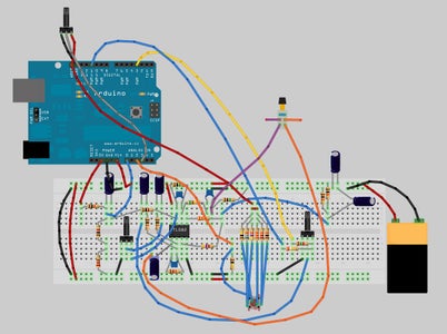
I have included the Fritzing file for this circuit if you want to look at it closer. The breadboard view and schematic view should be relatively accurate. However, the PCB view has not been touched and probably will not work at all. This file does not include the input and output jacks.
Attachments

Step 9: Cut Brackets

Cut out two brackets using the template file attached to this step. They both should be cut out of non-conductive material.
I cut out the larger base bracket out of a thin cork mat and the smaller potentiometer bracket out of 1/8" rubber.
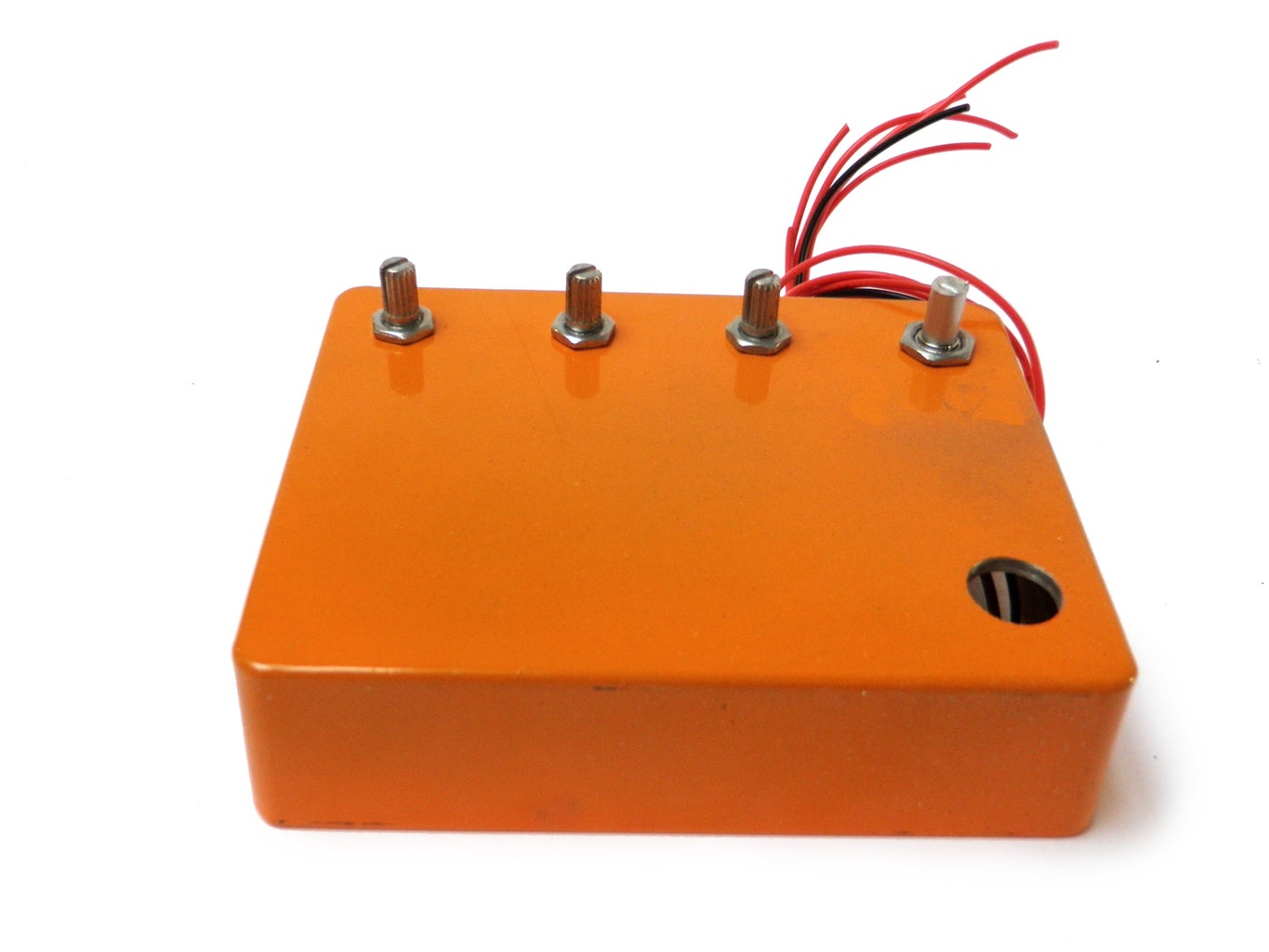
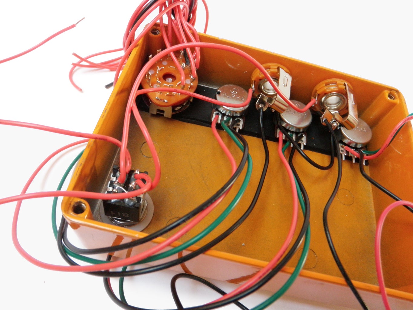
Step 10: Insert Knobs
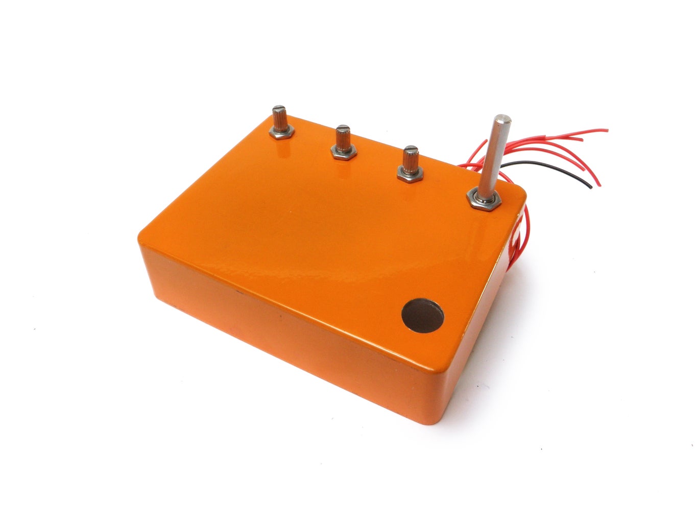


Place the rubber bracket on the inside of the case so that it aligns with the drilled holes.
Insert the potentiometers up through the rubber bracket and the 9/32" holes in the case and lock them firmly in place with nuts.
Install the rotary switch in the same fashion in the larger 5/16" hole.
Step 11: Trim
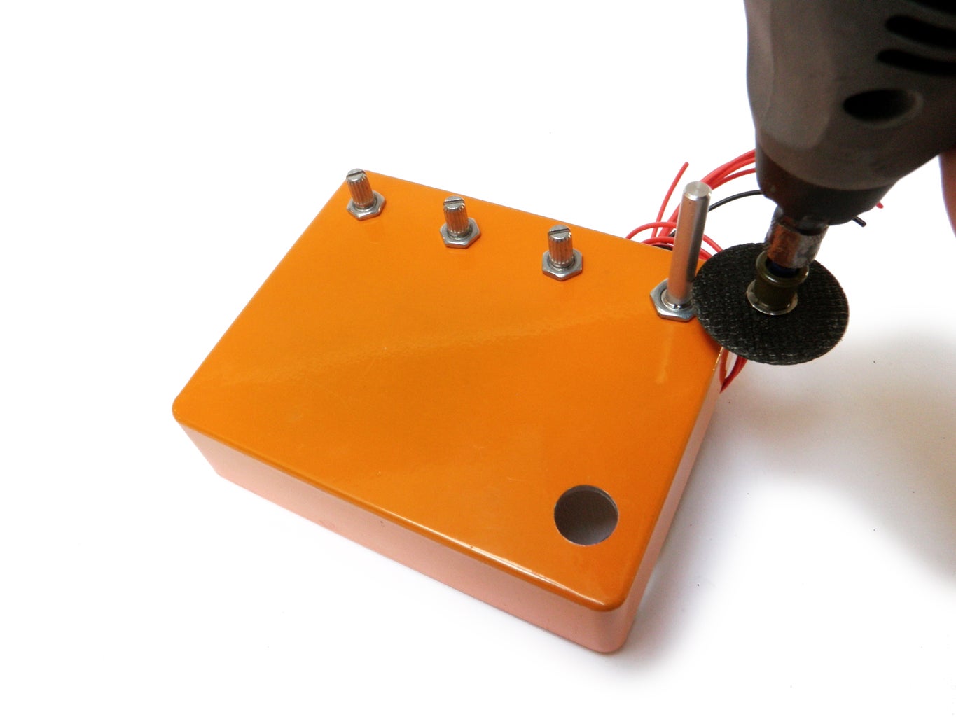
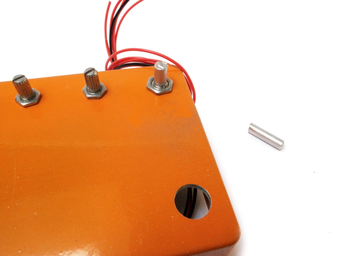
If you use long shaft potentiometers or rotary switches, trim them down such that the shafts are 3/8" long.
I used a Dremel with a metal cutting wheel, but a hacksaw will do the job too.
Step 12: Switch

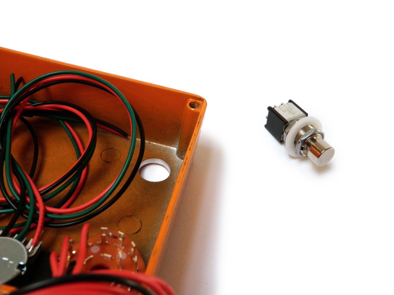
Insert the foot switch into the larger 1/2" hole and lock it in place with its mounting nut.
Step 13: Stereo Jacks
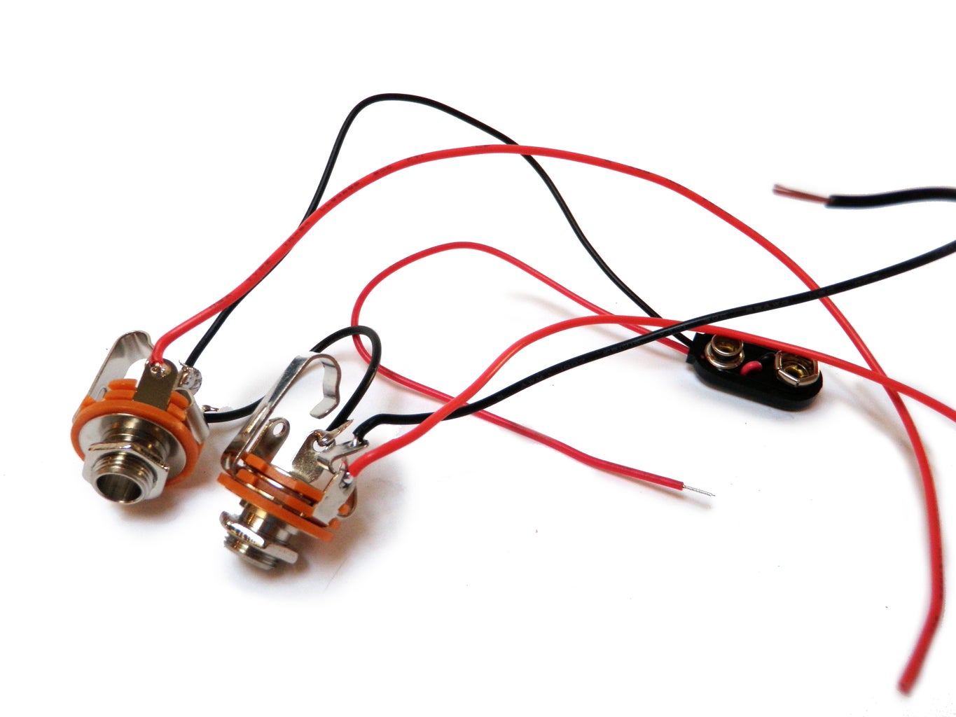

We will be using stereo jacks for what is fundamentally a mono circuit. The reason for this is that the stereo connection will actually serve as the power switch for the pedal.
The way this works is that when mono plugs are inserted into each of the jacks, it connects the batteries ground connection (which is connected to the stereo tab) with the ground connection on the barrel. So, only when both jacks are inserted can ground flow from the battery to the Arduino and completed the circuit.
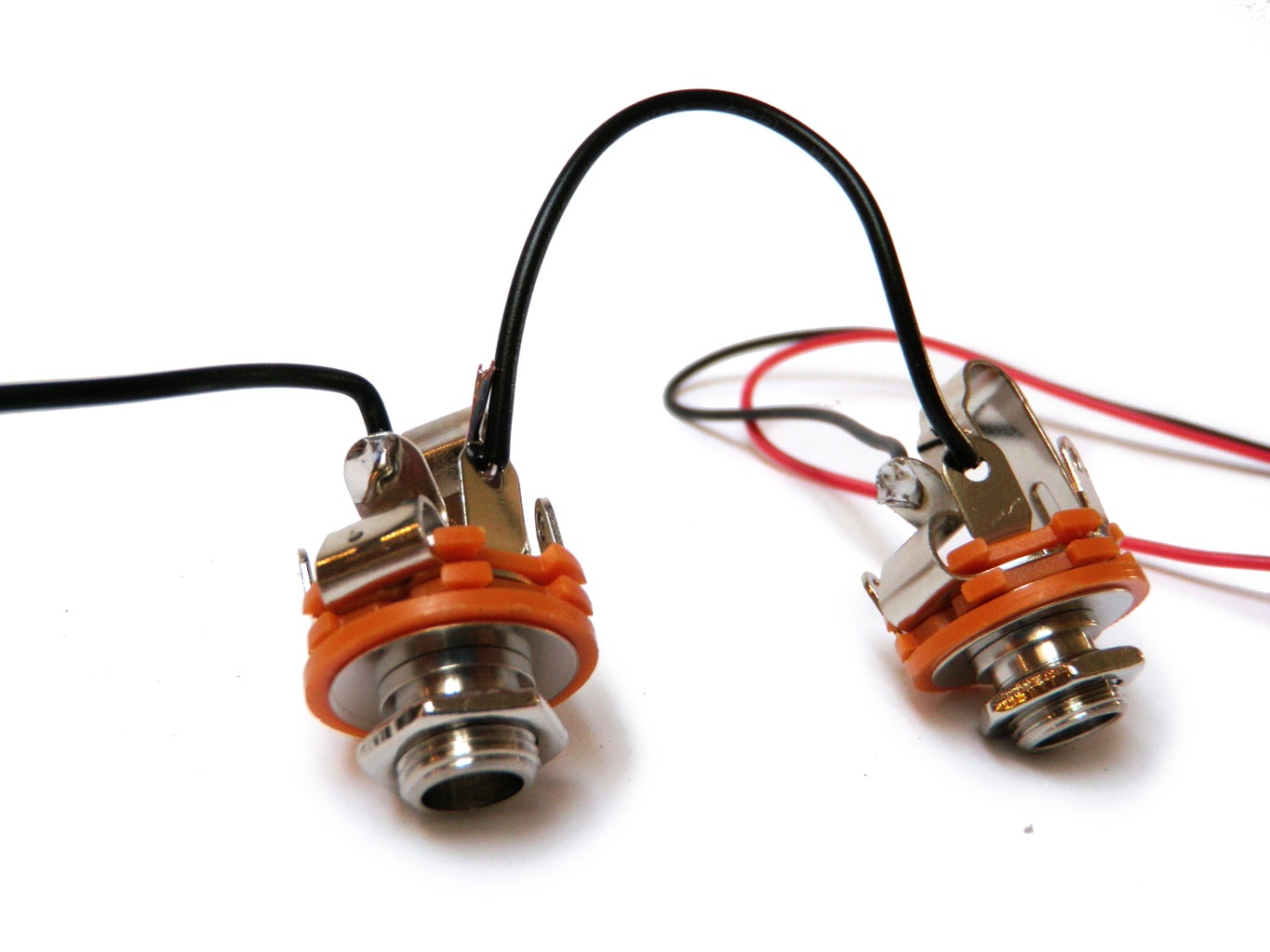
To make this work, first connect together the ground tabs on each jack with a short piece of wire.
Next, connect the black wire from the battery snap to one of the stereo audio tabs. This is the smaller tab that touches the jack about halfway up the plug.
Connect a 6" black wire to the other stereo tab on the other jack.
Lastly, connect a 6" red wire to the mono tabs on each of the jacks. This is the large tab that touches the tip of the male mono plug.
Step 14: Insert Jacks
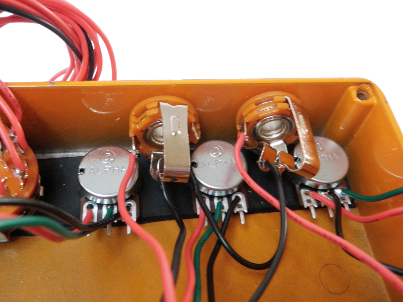
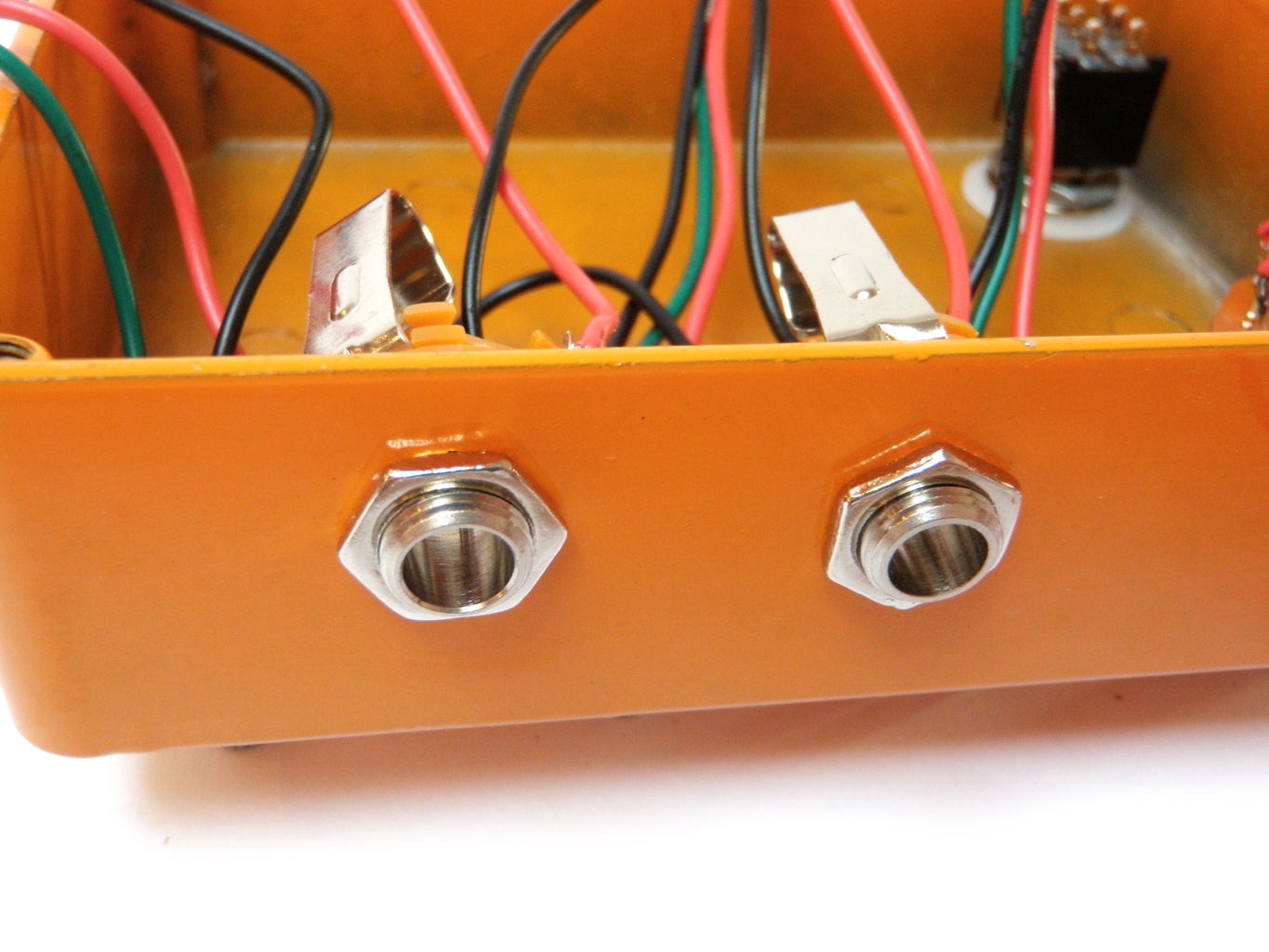
Insert the two audio jacks into the two holes in the side of the case and lock them in place with their mounting nuts.
Once installed, check that none of the metal tabs on the jack are touching the body of the potentiometers. Make adjustments as necessary.
Step 15: Wire the Switch

Wire one of the outer pairs of the DPDT stomp switch together.
Wire one of the jacks to one of the center pins on the switch. Wire the other jack to the other center pin.
Connect a 6" wire to each of the remaining outer pins on the switch.
The wire that is in line with the jack on the right should be the input. The wire that is in line with the switch on the left should be the output.
Step 16: Finish the Wiring
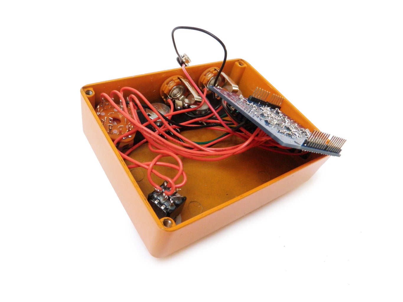
Trim the wires attached to the components installed inside the case to remove any slack before you solder them to the Arduino shield.
Wire them to the Arduino shield as specified in the schematic.
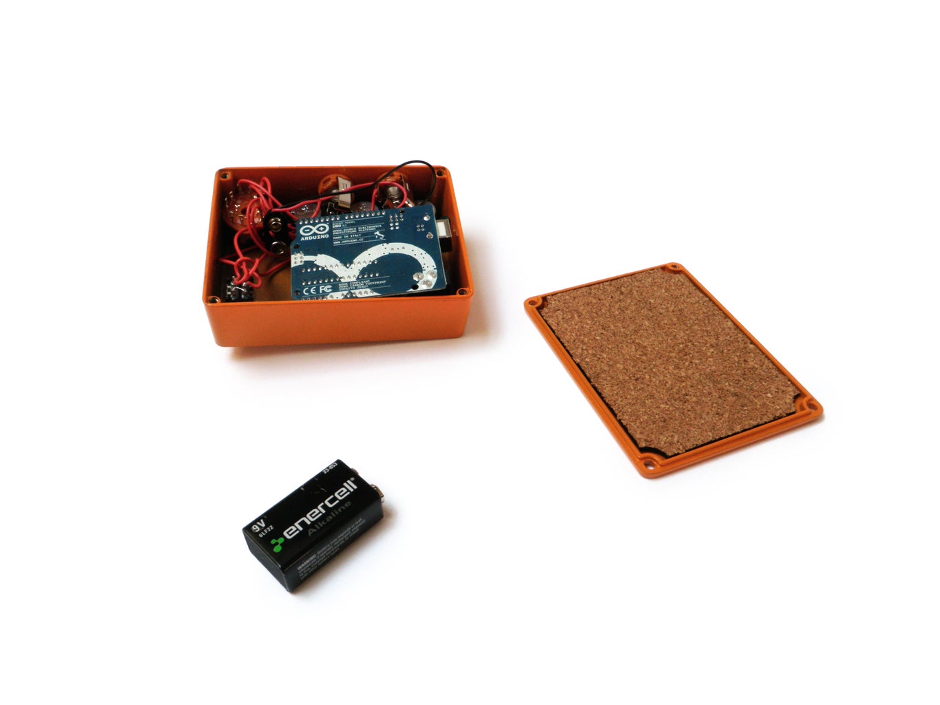
Step 17: Cork

Affix the cork mat to the inside of the case's lid. This will keep the pins on the Arduino from getting shorted on the metal of the case.
Step 18: Program

The code that this pedal is largely built upon ArduinoDSP which was written by Kyle McDonald. He did some fancy things like mess around with the registers to optimize the PWM pins and change the analog reference voltage. To learn more about how his code is working, check out his Instructable.
One of my favorite effects on this pedal is a slight audio (distortion) delay. I was inspired to try creating a delay line after seeing this really simple code posted on Little Scale blog.
The Arduino was not designed for real-time audio signal processing and this code is both memory and processor intensive. The code that is based on the audio delay is especially memory intensive. I suspect the addition of a stand-alone ADC chip and external RAM will greatly improve the ability for this pedal to do awesome things.
There are 6 spots for different effects in my code, but I have only included 5. I have left a blank spot in the code for you to design and enter your own effect. That said, you can replace any slot with any code that you wish. However, keep in mind that trying to do anything too fancy will overwhelm the chip and keep anything from happening.
Download the code attached to this step.
Attachments
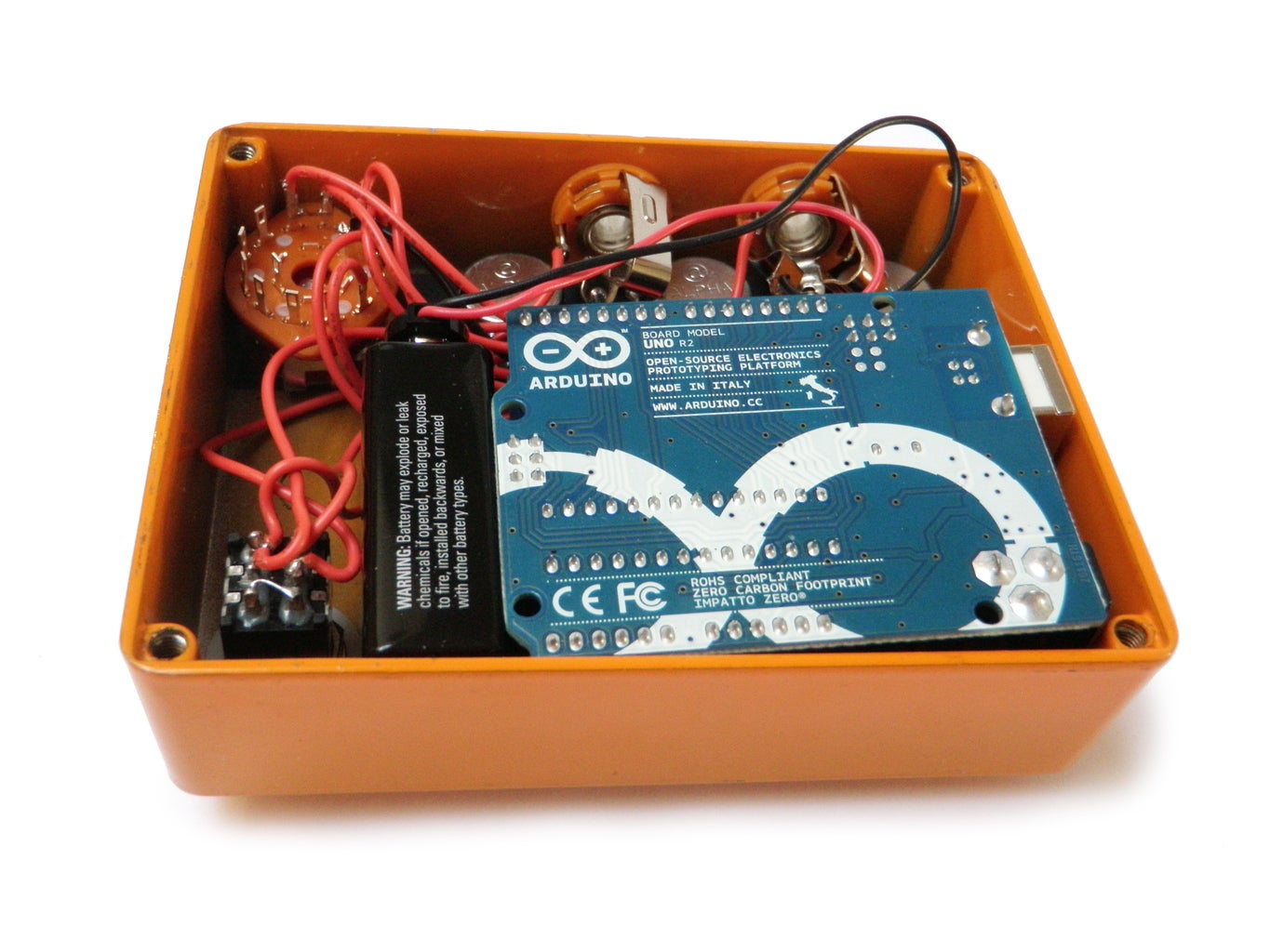
Step 19: Attach
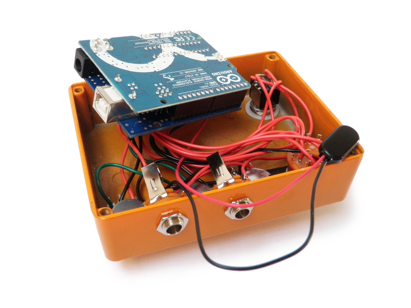
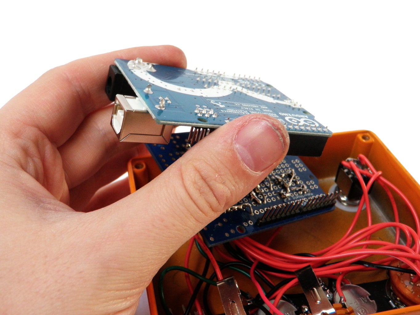
Attach the Arduino to the shield inside the case.
Step 20: Power
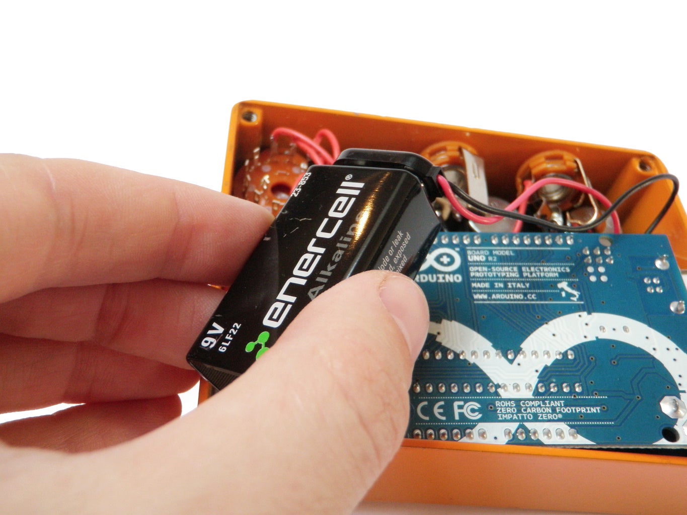
Plug in the 9V battery to the 9V battery connector.
Carefully situate the battery snugly between the DPDT switch and the Arduino.
Step 21: Case Closed


Put the lid on and screw it shut.
Step 22: Knobs
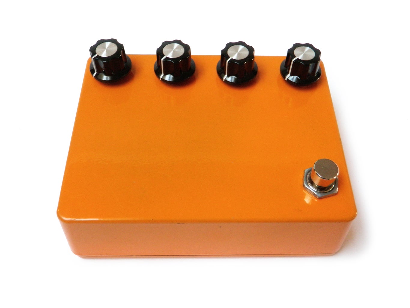
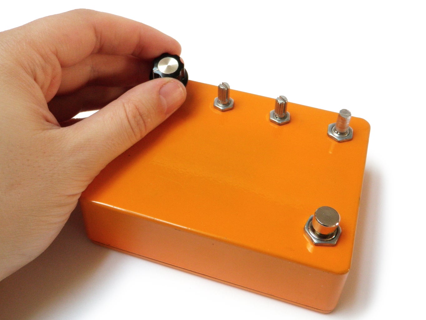
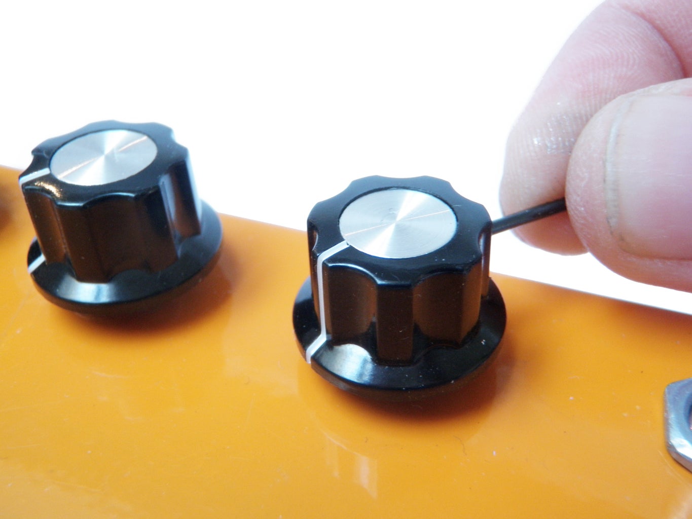
Place knobs onto the potentiometer and rotary switch shafts.
Lock them in place by tightening the set screws.
Step 23: Plug and Play
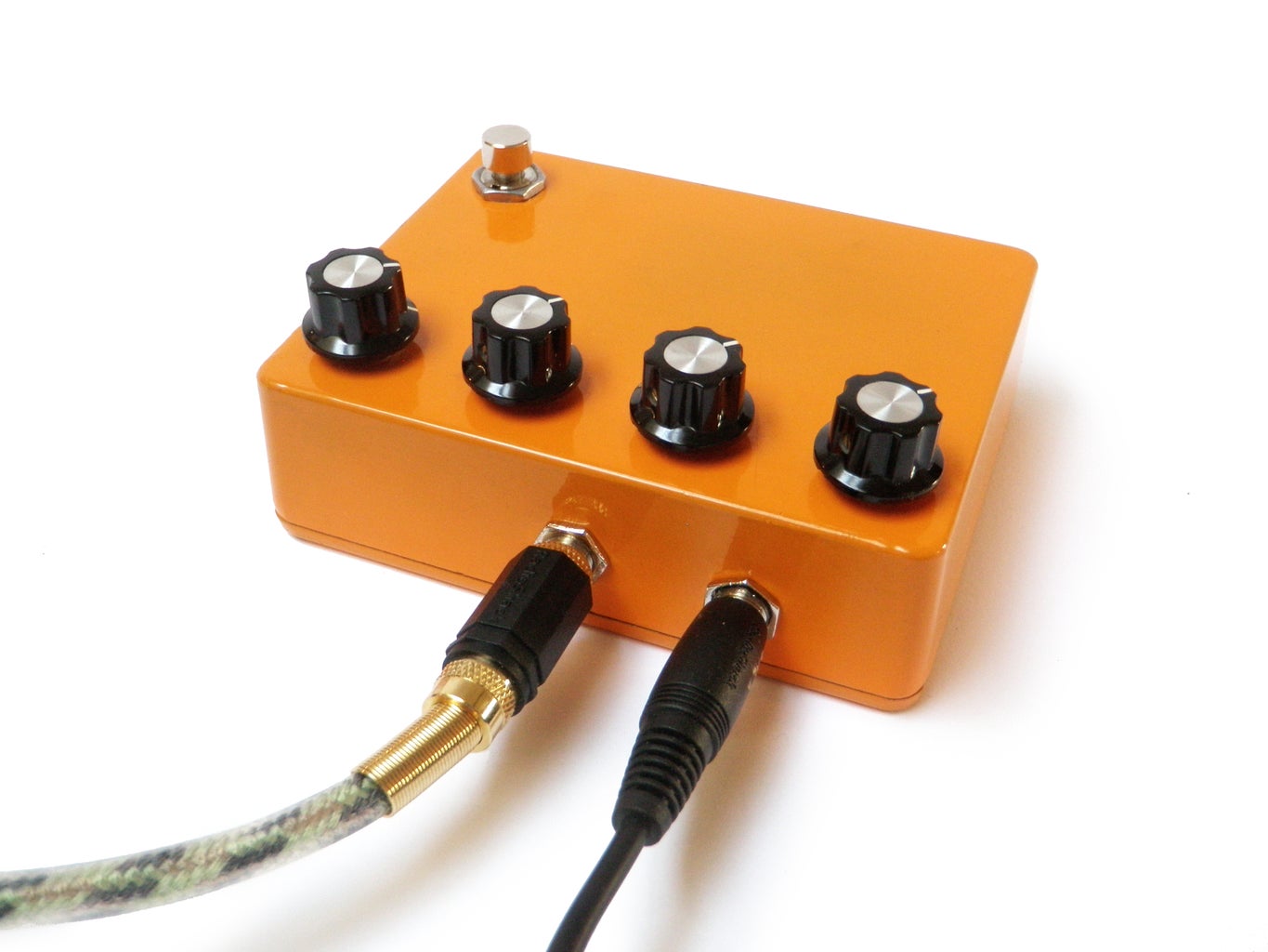
Plug in your guitar to the input, connect an amp to the output, and rock out.

Did you find this useful, fun, or entertaining?
Follow @madeineuphoria to see my latest projects.

Participated in the
Arduino Challenge

Participated in the
Make It Real Challenge


