

Introduction: Arduino Home Automation Outlet Box


ITS DONE! CHECK OUT THE VIDEO IN THE LAST STEP!
So in my apartment we are supposed to have a switched outlet so that you can turn a light on as soon as you enter the apartment. I have been unable to find said outlet. So i figured that I would finally find a "permanent" use for my Arduino since it has been sitting in its boxed unused for months.
So i decided i would put my Arduino to good use and use it to create a webserver, and website for the Arduino to serve up which would control up to 8 outlets. I decided to use and ammo can for durability and portability as well.
-------------------------DISCLAIMER-----------------------------------
I TAKE NO RESPONSIBILITY FOR YOU ZAPPING THE CRAP OUT OF YOURSELF
YOU ARE DEALING WITH 120V AND POTENTIALLY DEADLY AMPERAGES.
PLEASE BE CAREFUL
Tools Needed
Impact Driver
Drill Bits
Dremel with Cutting Wheel
Supplies Needed:
(prices are per each item)
1 x .30 cal Ammo Can ($9.99)
1 x 8 Relay Sainsmart Module ($15.00)
1 x Arduino Uno Rev 2 (I already had one, but they cost around $30)
1 x Seeduino Ethernet Shield ($29.99) [this has a Wiznet 200 chip and you need a modified Ethernet Library to get it to work]
1 x 6 Bay Terminal Block ($2.99)
1 x Cat5 Cable (I bought mine while I worked at Best Buy a while ago, but actual cost is $12.99)
1 x USB B to A Cable (had this forever) [for on the go programming and power to the Arduino. My wireless router has a USB port so i use to power the Arduino]
4 x 15 Amp Outlets ($2.19)
[i like these because they are square and come in grey, so they look better protruding from the box]
http://www.homedepot.com/p/Leviton-Decora-15-Amp-D...
1 x Short Length of 1/4" OD Rubber Hose ($ price not available, havent bought it yet)
[use it for the cutout for all the wires]
Misc. 14 Gauge Stranded Wire in Red, White and Green ($ price not available, havent bought it yet)
14 Gauge Ferrules ($ price not available, havent bought it yet)
14 Gauge Fork Lugs ($ price not available, havent bought it yet)
Step 1: Coding
I host a website that acts as my personal web portfolio. I hosted the stylesheet there, and then the arduino webserver pulls the styling from there.
Stylesheet -- http://www.ryanblajda.com/wp-content/uploads/2014/...
I attached my code file. I want to incorporate the Time Library so the Home tab actually does something. I will have it probably display the temperature and time (but it will only display the time that you loaded the website.) Im not the best programmer so its all pretty simple.
Attachments

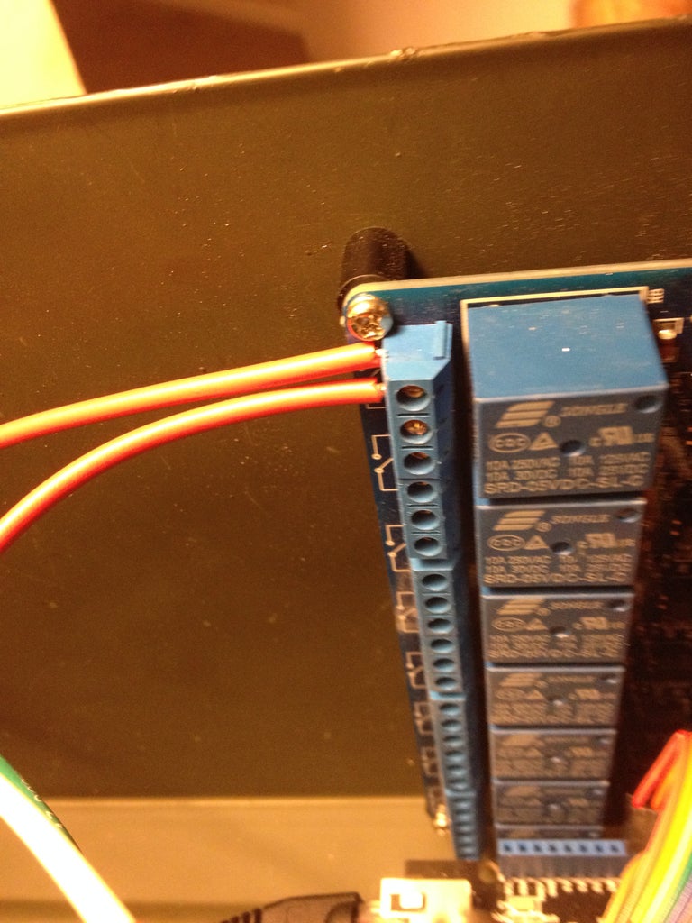
Step 2: Mount Arduino & Relay Module


So now that you have your Arduino programmed, you need to mount it, as well as your relay module. I chose to mount mine in the back of the can so that i could loop the Cat5 and USB cables out the back of the Ammo Can. I eventually want to incorporate IR control, so i will eventually attach a 1/8" jack that will connect to an IR emitter.
I used plastic standoffs on the relay module and metal ones on the Arduino. I wanted to try and keep the relay module as isolated as possible. I also have a terminal block to use going from the IEC port to the circuits and the relay module.
Ferrules are your friend. they are made to fit into the relay modules Phoenix style connectors.
Step 3: Dremel Hole for USB and CAT5 Wires


So now that its mounted, cut out a nice square hole for your wires to come out of. Then use that 1/4" hose to line the metal so it doesn't chafe the cables.
Originally I wanted to use Panel Mount USB and CAT5 cable adapters because it would look neater, but I wanted to save money, I havent gotten the rubber hose yet, but i will add it once i pick some up.
Step 4: Mount NPT Gland and Terminal Block


So I do want it to be kind of neat/professional so I purchase an NPT valve/gland for the S/O cable that will be made into the power cord.
Step 5: Mount Your AC Power Outlets & Wire It All Up!


So mount your AC power outlets, then ferrule all your wires after making them to length and wire it up!!
Step 6: Hook It Up and Enjoy
So, all you have to do now, is hook it up and see how it works!!

Participated in the
Tech Contest

Participated in the
Microcontroller Contest


