

Introduction: Arduino Home Basketball Hoop Score Detection System A.k.a. ScoreKeeper


My little sister and I found this indoor basketball hoop (pictured above) at a dumpster a few weeks ago. We were coming home from church just as two people were unloading it from their truck. We decided to grab it, along with the air hockey table the couple were throwing out. We figured we would do some hacking so, we started to think, "Hmm, I wonder if there is a way to detect when a ball has gone through the hoop?" Our first thought was to use an ultrasonic distance sensor and place it right below the rim. I was a little worried because I wasn't sure if the net would occlude the distance sensor and make the results erratic. It turns out that this works pretty well actually. The sensor peers through a gap in the net and easily detects when a ball goes through.
Next, we needed to decide what we were going to use as the scoreboard. Our first thought was to buy a large seven segment display. We found some online, but a relatively large display (5 inches or taller) gets kind of expense (~$15). And we needed 2 of them, plus another 3 for another project we were planning. Thought there had to be another alternative. Then we found this Instructable by Kurt E. Clothier. Kurt used individual LEDs to make a custom 7-segment display. He was able to diffuse the light of the each LED to properly created a lit "segment" using hot glue. This is the approach we have taken. Thanks Kurt!
Please enjoy this step by step Instructable on how to set up your own Score Detection Hoop System or Scorekeeper.
Step 1: Gather Your Tools


1 x indoor basketball hoop
1 x breadboard (perfboard would be better, there are a ton of connections so it would be best to solder everything together)
1 x indoor basketball
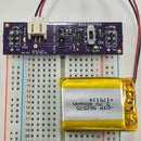
1 x Arduino (I used an Arduino Pro Mini, but any Arduino will do)
1 x battery for external power
1 x 16-Channel Multiplexer (I used CD74HC4067)
1 x 200 Ohm - 1 kOhm resistor
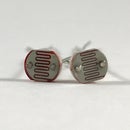
1 x Ultrasonic distance sensor (I used HC-SR04)
28 x LEDs
Lots of wire
Hot glue
14 pieces of aluminum foil
Appropriate material for the baseboard
NOTE: the supply voltage for the multiplexer and distance sensor are 5 V. I say this because most of the times, when we apply external power to the Arduino, it is with a 9 V battery. Just make sure you are taking power from the 5 V pin (or VCC if you use the Pro Mini), not Vin (or RAW if you use the Pro Mini).
Step 2: Preparing Your Base Board for the LED


You want a sturdy surface for the baseboard. We chose cardboard, but you should use something more fire-safe. It is a good idea to draw out the 7-segment display and map out where you are going to put the LEDs. After you have decided where you are placing your LEDs, go ahead and glue the aluminum foil onto the baseboard. The aluminum foil should outline the 7-segment. The LEDs will be oriented at a 90 degree angle relative to your direction of viewing. So, most of the light is not pointing to you. The aluminum foil reflects the light back to your eye.
Step 3: Placing Your LEDs


Each segment has two LEDs at opposing ends of the segment. The LEDs will are bent at a 90-degree angle and point towards the inside of the segment. Cut out or bore some holes for your LEDs. DO NOT ALLOW THE LEADS OF THE LED TO COME IN CONTACT WITH THE ALUMINUM FOIL. Aluminum foil is a conductor so it will short out the LEDs. After you have your LEDs placed correctly, it is time to lay the hot glue. You want hot glue to be over top of the bulb of the LEDs and between the LEDs, effectively connecting the two LEDs. The hot glue diffuses the light along the entire segment.
Step 4: Solder Your LEDs


This is the tedious part. Solder wire to each lead of the LED. To make this a little easier, You could solder all the ground pins together and then make a single connection to your power supply ground. We connected the two LEDs that make up a single segment in parallel.
Remember, the longer pin of the LED is the anode, and the shorter pin is the cathode. The anode will be connected to the output of the multiplexer and the cathode will be connected to ground. The direction of current flow is anode to cathode.
Step 5: Control Logic for 7-Segment Display


There are many ways to control a 7-segment display. The easiest would be to wire each LED to a digital pin on the Arduino. This is undesirable for many reasons. First of all, you would not have enough digital pins to wire to each segment or provide enough current to light each LED simultaneously. To counter these two problems, the common technique is to multiplex the segments. Usually, this is done with shift registers, but we decided to use an analog multiplexer instead. A multiplexer allows a single input to be sent to several different outputs by controlling a few logic selector pins. Note, the multiplexer can only output to one channel at a time. The multiplexer we used has 16 channels. The active channel is determined by 4 selector pins (S0-S3). The trick into making the multiplexer display a number on our custom 7-segment display is to quickly change the channels that the multiplexer is outputting to. For example, if we wanted to display the number 2, we would need to light up segments A, B, D, E, and G. With our multiplexer, we would output to the channels that are attached to each segment. We would need to switch from one channel to the next so quickly that the human eye will see all the channels lit at once and subsequently, the number "2."
Oh, I forgot to mention, I wrote an Arduino library for the multiplexer. I needed a multiplexer for this and other projects so I figured that I would go ahead and write a library for it. The multiplexer library is for easy control of a single multiplexer with N number of channels up to 32 channels. It was meant to be extremely simple and to the point. There are plenty of other libraries on the web if you want to use a different one. Keep in mind that you would need to modify the scoreKeeper.ino code that we will be giving you. Please add Mux.h and Mux.cpconsult the Arduino website on how to import a library if you do not know how to do so.
The main functions of the library that you need to be concerned with is the constructor and the open() function. The constructor initializes a single multiplexer. The open() function takes a single parameter which is the channel that you would like to output to. The library is sufficiently commented if you have any questions.

Step 6: Wire Up the Multiplexer

The wiring for the multiplexer is simple. The selector pins S0, S1, S2, and S3 are wired to digital pins 2, 3, 4, and 5 respectively. The selector pins determine which channel of the multiplexer is active. Additionally, the enable pin (E) is wired to digital pin 6. The enable pin, enables or disables the multiplexer from outputting to a channel. If the enable pin is high, the multiplexer is disabled. If the enable pin is low, the multiplexer is enabled. You may be tempted to leave this unwired or permanently wired to power or ground, do not. Otherwise, you will get a sporadic display.
The common input pin (the signal that will be sent to each LED on our custom 7-segment display), is wired to our positive voltage rail via a resistor. Notice that when we set up the LEDs we did not put a resistor in series to limit the current. This is because we are using a resistor at the common input pin of the multiplexer to the limit the current. This way, we only need on resistor the entire display.
Step 7: Wiring Up 7-Segment Display

Remember, the two LEDs that make up a single segment are wired in parallel. Then, connect each segment to a single output channel on the multiplexer. I wired the segments in the following order: for the tens digits, segments A-G are wired to channels 8-14 (respectively) on the multiplexer. For the ones digit, segments A-G are wired to channels 0-6 (respectively) on the multiplexer. If you change these connections for any reason, you must modify the code.
Remember, the longer pin of the LED is the anode, and the shorter pin is the cathode. The anode will be connected to the output of the multiplexer and the cathode will be connected to ground. The direction of current flow is anode to cathode.
Step 8: Ultrasonic Distance Sensor


Setting up the ultrasonic distance sensor is pretty straightforward. There are a ton of tutorials online for the sensor so I will just give you the information. The concept behind the sensor is pretty simple. The "trigger" pin sends out a sound wave. The sound wave bounces off the closest object and back to the sensor and hits the "echo" pin. Based upon the time it took for the ping to be sent and received and the speed of the sound wave, we can calculate the distance the object is from the sensor. The code for this is also pretty simple.
The distance sensor is placed below the rim. There just happens to be one of those spaces in between the next so that the sensor is not occluded.
//double distance()
//@return      the distance in centimeters (cm)
//Calculates the distance from the sensor to the next closest
//object.
double distance()
{
  double duration = 0;
  digitalWrite(trigPin, HIGH); //send out pulse
  delayMicroseconds(50); //give the pulse time
  digitalWrite(trigPin, LOW); //turn off pulse
  duration = pulseIn(echoPin, HIGH); //read echo pin

  return (duration/2) / 29.1; //in cm
}
Step 9: Code
Controlling the Multiplexer
Download the code from the ScoreKeep GitHub Repository, or from the attached file below.
To summarize, the segment is controlled using a multiplexer which outputs to a different segment every millisecond. I used a timer interrupt to ensure the timing was precise. A timer interrupt does exactly what it says. It interrupts the code at precise time intervals to execute commands written in the accompanying interrupt service routine (ISR). A good tutorial on Arduino timer interrupts can be found here.
The timer interrupt in this code outputs to a single segment using the multiplexer. On the next iteration of the ISR, the code outputs to another segment and so on. So, if we would like to display the number 22 (segments A, B, D, E, and G of both the tens and ones digit), the code would output to segment A of the ones digit on the first iteration, then to segment B, then segment D, then segment E, then segment G, all of the ones digit. On the next iteration, the we output to segment A of the tens digit, then segment B, then segment D, then segment E, then segment G. Afterwards, we start from segment A of the ones digit again and repeat until the number we need to display changes.
//Interrupt Service Routine
//Displays the numbers for the score on the 7-segment display.
//It lights a single segment every 1 ms incrementing the segment index every iteration.
ISR(TIMER1_COMPA_vect)
{
  //Ones digit
  if (index < 8) {
    if (bitRead(HEXvalues[score%10],index))
    {
      myMux.open(index);
    }
    index++;
  }
  //Tens digit
  else if (index >= 8 && index < 16) {
    if (bitRead(HEXvalues[score/10],index-8))
    {
      myMux.open(index);
    }
    index++;
  }
  //resets index
  else {
    index = 0;
  }
}
Detecting a score
Using the distance sensor code, we use the distance returned and check if it is below a "scoreThreshold." If the distance to the next closest object gets really close, then it must be a ball going through the hoop. Additionally, I have added a refractory period for detecting a shot. This means, when a shot is detected at time t, then another shot cannot be registered until a certain amount of time after time t. I think I chose 2 seconds, but you may choose to increase or decrease this as you see fit. This is done because the loop() function of the Arduino runs so quickly that it would register the same shot more than once as the ball moves through the hoop.
//boolean detectScore()
//@return      true if shot is detected, false if otherwise
//
//Detects whether or not a shot was made by checking if the
//distance from the ultrasonic distance sensor to the next closest
//object is under the "threshold" used to determine when a shot
//was made.
boolean detectScore()
{
  return (distance() <= scoreThreshold);
}

//double distance()
//@return      the distance in centimeters (cm)
//Calculates the distance from the sensor to the next closest
//object.
double distance()
{
  double duration = 0;
  digitalWrite(trigPin, HIGH); //send out pulse
  delayMicroseconds(50); //give the pulse time
  digitalWrite(trigPin, LOW); //turn off pulse
  duration = pulseIn(echoPin, HIGH); //read echo pin

  return (duration/2) / 29.1; //in cm
}
Increment score
Increments the score by one point when a score is detected.
//void incrementScore()
//Increments the score variable by 1.
void incrementScore()
{
  score += 1;
}
Attachments
Step 10: Demo

Participated in the
Make it Glow!

Participated in the
Homemade Gifts Contest


