

Introduction: Arduino IoT Robotic Arm


Hello there! This is my first robotic arm with the following features (until now):
- 5DOF robot, actually 4 if we exclude the gripper
- the brain is an Arduino Yun with IoT capabilities
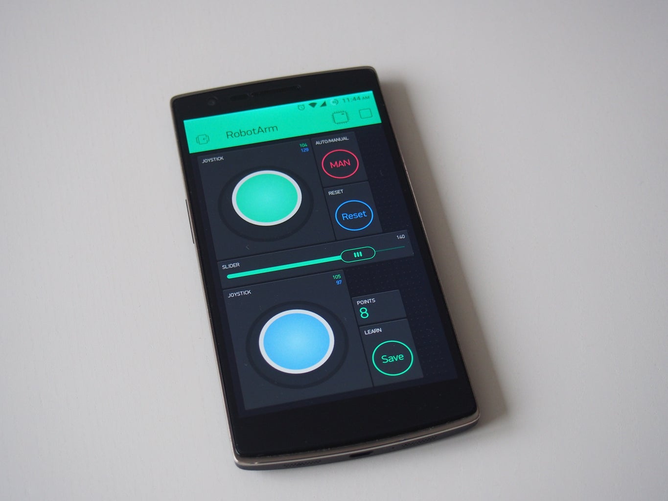
- the control interface is built in Blynk app
- forward kinematic are implemented in Matlab using the Robotics Toolbox
- a new library that I wrote which realizes a smooth motion
I am very happy with the result. Therefore, I would like to share with you my experience and how to build it. So, let's start...
Step 1: Components & Materials

To build the robot you need:
- 1 x Arduino Yun (or any Arduino board)
- 5 x servo motors
- 1 x 5V charger, min 2.5 A
- 2 x Led's
- 2 x resistors, 100 ohm (for red led) and 150 ohm (for blue led), respectively
- 2 x wood mixing sticks
- 1 x metallic wire (or similar)
- 1 x plastic sheet (I took it from a shower gel bottle)
- 1 x rubber band
- 2 x small sponges (see left-upper corner)
- 9 x plastic M3 screws
- 6 x plastic M2.5 screws
- 1 x wood plate 3mm (30cm x 50cm should be more than sufficient)
- 1 x wood glue
- time for coding
Step 2: Building the Robot


For building the robot, start by measuring the servos size and checking the servos torque. This will give you an indication about the size of the arms and eventually the size of the robot. In my case, I ordered 2 different micro high-torque servos: first pair and second pair. These can travel up to 140 deg even though they are specified to travel 120 deg. However, I advise to buy 180 deg servos in order to have more travel angle.
For the gripper, there is no need for a high-torque servo. The cheapest micro-servo on ebay can do the job.
Start by cutting the arms as you see in Photo 1. Here, you can be creative, there is no fixed design, you can come up with your own design. Then, build the gripper using one mixing stick cut in half and the plastic sheet as spring return. With wires connected to inner side you can close and open the gripper. For my robot, I used one M3 screw to make the gripper pivot. The gripper pivoting is done by a servo located to the other side of the arm in order to obtain weight balance. The power is transmitted via another mixing stick (see Photo 2, top of the robot).
Next, build the base and the plate that holds the base servo and the Arduino Yun board (or another board). Put everything together and you should have something like in Photo 2.
If you want a better looking design, sand the wood components and paint them (as in Photo 3) with your preferred color. For my robot, I went for a silver color (to mimic metal) with red stripes.
And yes.. we have a robot :) see Photo 4.
Step 3: Writing the Code

Ok, so we finished making the hardware! However, the robot has no life without software.
For the software, I started by making first an interface in Blynk. If you haven't used Blynk before, please check their website on how to do it. Should be very easy and straight-forward.
Note: If you don't have a board that can connect to the internet, don't worry you can still use Blynk with a normal board e.g., Arduino Uno, via the USB port. To do this read here.
Next, let's go to Arduino IDE and write some code. For your convenience, I attached the code, so you can just use it :) To run it you need to do the following:
- Configure the Arduino Yun board.
- Install Blynk library in your Arduino IDE by going to Sketch>Include Library>Manage Libraries , search for Blynk and install it.
- Add the SimpleTimer library in a folder with the name SimpleTimer to your Arduino library folder, usually Arduino\libraries\
- Add the MotionGenerator library that I wrote, in a folder with the name MotionGenerator to Arduino library folder
- Compile and upload RobotArm_instructables.ino (Note: don't forget to update your Blynk token)
Note: The MotionGenerator library is an analytical-based solution that will give you smooth nice transitions from one point to another. It allows limitations on the maximum speed and acceleration.
_____________________________________________
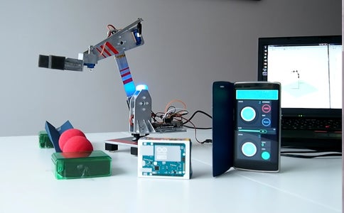
Optional steps (forward kinematics, see Photo 2): For this you need Matlab and Robotics Toolbox. If you have all these set, make sure your robot is connected to Blynk and connected to your computer's USB port. Matlab will collect information from the Arduino via the serial communication. So, make sure to fill in the right COM port in the MainScrip.m. Finally, just run the MainScrip.m.
Note: The robot kinematics are for my own robot. For your robot the dimensions might be different (feel free to adjust in robotKinematicsFcn.m).

Step 4: Testing and Having Fun
Great! You completed the Robot Arm. Now is time to play and enjoy!
In the future, I will implement inverse kinematics and perform tasks like drawing, precise gripper positioning, trajectory following and many more. So, stay tuned!

Participated in the
IoT Builders Contest

Participated in the
Arduino Contest 2016


