

Introduction: Arduino Keypad Door Lock


In this instrutable I will explain how to do keypad door lock from arduino and XHQ-PT.
XHQ-PT is an engine stop solenoid used to shutdown most chines diesel generator ,I couldn't find a suitable actuator for my door in the local market ,so I decide to use this one.
Required Parts:
1- Arduino Nano or (Arduino Pro Mini 5 volt type with UART programming Module ).
2- XHQ-PT (12 Volt type).
3- 4*4 membrane keypad.
4- 12 Volt Relay.
5- BC547 NPN transistor.
6- 4.7 Kohm resistor.
7-100 nF Ceramic capacitor.
8- 7805 Voltage Requlator.
9- 2 rectifier Diode.
10- Pitch Pin Header.
11- PCB Board or bread board.
12- 12Volt 1amp power source.
Step 1: How XHQ-PT Work

XHQ-PT consist from three wires :
Red : Connect To positive(+) 12 Volt.
Yellow : Connect to Negative (-).
Green or Blue: Signal wire (Pilot).
if you connect positive 12 volt to signal wire the actuator will pull the steel wire 4 cm then stop.
when positive 12 volt removed from signal wire the steel wire will return to actual location.
The length of steel wire around 1 meter so it can be designed depend on your choice.
Working Current :0.5 Amp.
Step 2: Testing the Code


First of all you need to download Keypad.h and password.h library from below webpage
http://playground.arduino.cc/Code/Password
http://playground.arduino.cc/Code/Keypad
Copy the extracted libraries in :
arduino-1.0.3\libraries\Keypad
arduino-1.0.3\libraries\Password
Rerun arduino sketch and open the attached file (DoorLockFinalVer.ino).
I used arduino Nano connected on breadboard in the attached picture to verify that everything configured correctly.
after uploading the code with no error type the password 1234* ,the result should be LED on pin13 ON for 1.5 Sec.
then OFF ,also you can open serial monitor for testing.
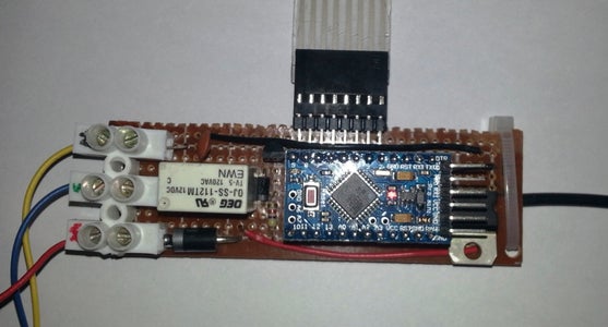
Once I finished testing stage I start to work on PCB and I replaced the Nano with Pro Mini to make the circuit smaller but you will need additional UART module to program the Pro-Mini type. .

Step 3: Circuit Digaram
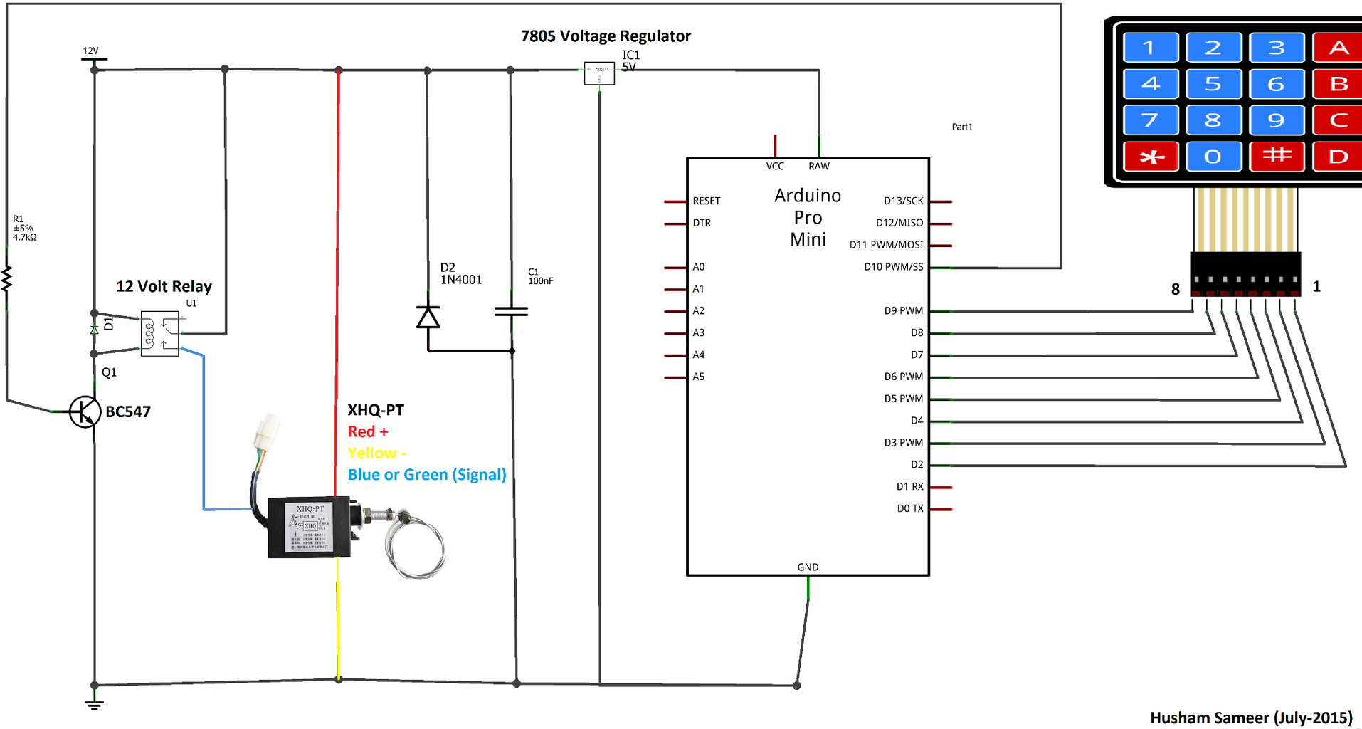

The attached picture showing the circuit diagram implemented on PCB ,Note that I fried two arduino board before this one because of the voltage spike generated by the actuator ,I fixed that by adding the fly back diodes to eliminate the sudden spike across the inductive load, also I added 100nF ceramic capacitor and additional 7805 voltage regulator.
the final result shown in below video.


