

Introduction: Arduino LED Display


My latest project (https://github.com/maciejmiklas/LEDDisplay) contains driver for 8x8 LED Modules controlled via MAX722xx. It allows you to build display of custom size that is only limited by the hardware itself. Vertical and horizontal size can contain up to 256 modules, but before reaching this limit you would run out of Slave Select lines for controlling MAX chips, or you would be limited by amount of RAM. The fact is: you can control reasonable amount of MAX chips and build display of custom size ;)
I've tested the whole idea on display that consist of 8 LED Modules in horizontal and 3 in vertical position. This gives us 24 modules which are containing 1536 LEDs (88 * 38).
Step 1: Hardware
Fritzing schematics are here: https://github.com/maciejmiklas/LEDDisplay/tree/master/doc/fritzing
First let's start with the controller, actually any Arduino will work, I've used Mega due to large number of digital output pins. You could also use Nano with shift register and alter way of addressing Select Slave lines in Display::send(...).
You will need extra power supply for driving LEDs - assuming that you are going to use more than one LED Matrix.
Step 2: Hardware - Driving Single LED Matrix Module


The schematics illustrate wiring of LEDs, MAX and Arduino. Both schematics are showing the same connection only from different perspective.
I've used the MAX7219 and 788BS LED Matrix, this is the one with common anode.
It might happen, that your LED Module has common cathode, in this case
you have to rewire connection to MAX chip. You just have to keep in mind, that MAX hat two sets of pins, that are relevant here: Dig0-Dig7 are supposed to be connected to cathodes (-) and SegA-SegG to anodes(+). Additionally such change will swap rows with columns within sine LED module.
Step 3: Hardware - Connecting All LED Matrix Together

In the previous chapter we've seen how to connect single LED Module with MAX chip. Now we will connect multiple LED Modules together into one large display.
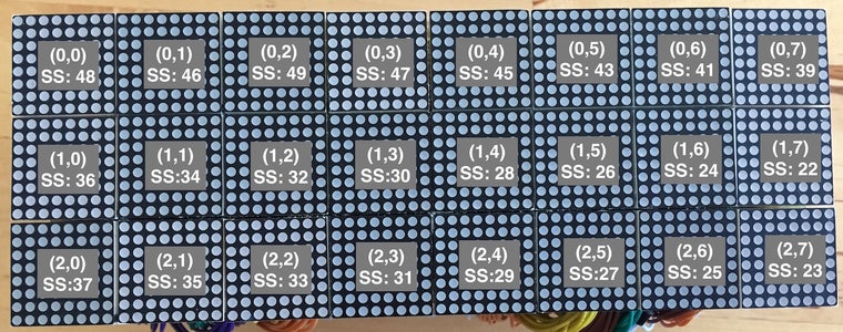
First picture shows the physical display that I've used for testing and examples. Each LED Module has label indicating its position and Select Slave line.
Second picture illustrates wiring between each LED module and Arduino.
Each 3-PIN connector on schematic above symbolizes one module
described in previous chapter (LED Matrix + MAX72xx), now we've connected all those modules together.
All MAX722xx chips share common MOSI and SCK lines, MISO is not used, each chip occupies separate Slave Select line.
The position of LED Matrix on the schematic above directly corresponds to their location on the physical display that I've used for testing. Additionally each module has description indicating it's position and Select Slave line, so for example: (2,1) SS: 35 gives us second module on third row (counting from zero) and PIN:35 on Arduino for Select Slave line.
Step 4: Software - Compiling
We are using standard Arduino libraries, so they are already available, the only exception is ArdLog. You have to import this LIB into your IDE. This basically means, that you have to download right release: https://github.com/maciejmiklas/ArdLog/releases/t... and unzip it into folder, where you usually place external libraries. In case of standard Arduino IDE on Mac it's ~/Documents/Arduino/libraries. On the end you should have following structure:
$ pwd
~/Documents/Arduino/libraries/ArdLog
$ ls
ArdLog.cpp ArdLog.h   LICENSE    README.md
Step 5: Software - Communication With MAX72xxx
We are using standard SPI library and Select Slave line on MAX chip for
addressing. MAX is configured in LED Matrix mode - so there is nothing special. The setup method can be found in: Display::setup()
Step 6: Software - Setting Things Up
The main class of our interest will be the Display - it's responsible for setup of MAX chips and provides API for painting.
Before we start painting it's necessary to set thing up. Code below creates 2D array containing Select Slave lines and initializes display. The display itself consist of 3 rows, each one has 8 LED Modules. Obviously you can choose any responsible size, but I will stick to this one.
The layout of mentioned 2D array corresponds to physical display: each LED Module has dedicated MAX chip, and each chip has dedicated Select Slave line. First dimension of our array indicates physical row on display, second dimension indicates LED Module within this row, and the value itself contains PIN number for Select Slave line.
#include "Display.h"
Display *disp;

/**
 * Orientation of LED Kits (8x8 LED matrix) on display that I've used for testing.
 * The numbers are indicating Select Slave line of MAX7219.
 * 48, 46, 49, 47, 45, 43, 41, 39
 * 36, 34, 32, 30, 28, 26, 24, 22
 * 37, 35, 33, 31, 29, 27, 25, 23
 */
ss_t **ss;

ss_t** createSS() {
  ss_t **ss = alloc2DArray8(3, 8);

  // first row
  ss[0][0] = 48;
  ss[0][1] = 46;
  ss[0][2] = 49;
  ss[0][3] = 47;
  ss[0][4] = 45;
  ss[0][5] = 43;
  ss[0][6] = 41;
  ss[0][7] = 39;

  // second row
  ss[1][0] = 36;
  ss[1][1] = 34;
  ss[1][2] = 32;
  ss[1][3] = 30;
  ss[1][4] = 28;
  ss[1][5] = 26;
  ss[1][6] = 24;
  ss[1][7] = 22;

  // third row
  ss[2][0] = 37;
  ss[2][1] = 35;
  ss[2][2] = 33;
  ss[2][3] = 31;
  ss[2][4] = 29;
  ss[2][5] = 27;
  ss[2][6] = 25;
  ss[2][7] = 23;

  return ss;
}

void setup() {
  util_setup();
  log_setup();

  ss = createSS();

  // Test display consist of 8x3 LED Modules (3 rows, each one 8 Modules)
  disp = new Display(8, 3, ss);
  disp->setup();
}
There is one more method worth mentioning: log_setup(). Whole
project has quiet precise logger - so that you can see what is actually happening. By default it's disabled, in order to enable it check out its documentation: https://github.com/maciejmiklas/ArdLog
Step 7: Software - Painting on the Display

Display consists of a few LED Modules, but form API perspective they are
connected together into one continuous canvas. You can place on this canvas bitmap on any position given by (x,y) coordinates from picture above.
The paint method has following syntax: paint(pixel_t x, pixel_t y, pixel_t width, pixel_t height, uint8_t data).
It allows you to paint a bitmap on given coordinates with limited width and height. So you can for example paint a bitmap on (3,4) that has 25x3 pixels. It might be larger than a actual display size - in this case it will get trimmed.
This is obvious and simple, but there is one catch - you have to provide right data. This is 2D array, where first dimension indicates vertical and second horizontal position on the display. Technically speaking data is flat array of pointers and each pointer points to array that represents one horizontal line on the display.
Moving over first dimension of data traverses over lines of the display. The second dimension of data represents horizontal pixels within single line, where each byte represents 8 pixels. Since our display consist of simple LEDs they can be either in on or off state, so each pixel is not being represented by one byte, but by one bit. In order to cover 16 pixels in horizontal position we need two bytes, 24 pixels require 3 bytes, and so on.
For example to fully cover display consisting of 8x3 LED kits (one used in our examples) we would need data[3][8]. Usually you will take array small enough to fit your bitmap and not one that will cover up whole display.
The paint(...) method updates internal buffer, in order to send content of this buffer to MAX chips you have to call flush(). The idea behind is to give you possibility to display few bitmaps on the display and after that paint the result. You can program few independent routines, that will update different part of the display and flush all changes at once.
Communication with MAX chips is not very fast and sending content of the whole display with every flush() is time consuming. You might be able to speed up this process by enabling double buffering (set DEOUBLE_BUFFER in Display.h to true). In this case flush() method will send only bytes that have changed, so you can call flush() with every loop and do not have to worry about loosing performance. The only drawback is increased usage of RAM: we are creating 2D array that allocates 8 bytes per each LED Kit plus few pointers that are usually required to maintain arrays.
2D arrays in this project have reduced memory footprint, because in order to create dynamic 2D array, we are creating actually 2 arrays with calculated offset (see: alloc2DArray8(....) in Util.h).
Step 8: Examples - Requires Libs
Examples are using ArdLog, so you have to import this lib into Arduino IDE. Here are instructions: https://github.com/maciejmiklas/ArdLog
Step 9: Examples - Simple Bitmap
In this example we will display simple static bitmap with 8x8 pixels.
Here is the Arduino sketch: SimpleBitmap, now lest go over it:
First we have to initialize display, as we have done in above in chapter Setting things up. Next we have to create data that can hold our bitmap - it will have 8x2 bytes. This gives us up to 8 lines and 16 horizontal pixels. But the size of our bitmap is 9x8 pixels (width x height) and this will be also the size of the painted rectangle. It should be as small as possible, so that you could place another bitmap right next to it.
The display will obviously only paint the rectangle given by width/height and not whole data array. This is normal, that data array can hold more pixels than accrual size of out bitmap, because size of data is a multiplication o 8 and bitmap not necessary.
void setup() {
  util_setup();
  log_setup();

  ss = createSS();

  disp = new Display(8, 3, ss);
  disp->setup();

  data = alloc2DArray8(8, 2);
  data[0][0] = B01100001; data[0][1] = B10000000;
  data[1][0] = B01100001; data[1][1] = B10000000;
  data[2][0] = B01100001; data[2][1] = B10000000;
  data[3][0] = B01100001; data[3][1] = B10000000;
  data[4][0] = B01100001; data[4][1] = B10000000;
  data[5][0] = B00110011; data[5][1] = B00000000;
  data[6][0] = B00011110; data[6][1] = B00000000;
  data[7][0] = B00001100; data[7][1] = B00000000;

  disp->paint(27, 9, 9, 8, data);
}

void loop() {
  util_cycle();
  log_cycle();

  // Paint method updates only internal buffer, in order to send data to
  // MAX chips you have to flush display.
  disp->flush();

  delay(100000);
}
Step 10: Examples - Static Text

Now we will display static text, actually those are going to be two independent lines.
Here you can find Arduino sketch containing whole example: StaticText.
Your sketch needs setup method as we've already seen above (chapter: Setting things up), so we will not discus it again.
In order to display text you should use StaticText8x8.
Font is defined in: Font8x8, each character has 8x8 pixels.
Your code could look like this one (plus initialization stuff from Setting things up):
StaticText8x8 *sta1;
StaticText8x8 *sta2;

void setup() {
  util_setup();
  log_setup();

  ss = createSS();

  disp = new Display(8, 3, ss);
  disp->setup();

  sta1 = new StaticText8x8(disp, 64);
  sta1->box(14, 2, "Hello");

  sta2 = new StaticText8x8(disp, 64);
  sta2->box(5, 15, "World !");
}

void loop() {
  util_cycle();
  log_cycle();
  disp->flush();

  delay(100000);
}
We have created two text areas, each one containing different text and being display one under another.
Step 11: Examples - Single Scrolling Text
This time we are going to display area containing text that will scroll
from left to right.
Lest analyze code (Arduino sketch):
Display *disp;

ScrollingText8x8 *message;
const char *textMessage;

void setup() {
  util_setup();
  log_setup();

  ss = createSS();

  disp = new Display(8, 3, ss);
  disp->setup();

  message = new ScrollingText8x8(disp, 48, 50, 5);
  message->init();
  textMessage = "This is an example of multiple scorlling areas ;)";
  message->scroll(8, 8, ScrollingText8x8::LOOP, textMessage);
}

void loop() {
  util_cycle();
  log_cycle();

  message->cycle();

  disp->flush();
}
The initialization of the display is the same as in examples above, so it's omitted here.
In order to display scrolling text we are using ScrollingText8x8. In setup() we are creating instance of this class and calling method scroll(...). This part only initializes scrolling, but does not play the animation itself. In order to play the animation you have to call cycle() and flush() in main loop and you must not have any additional delays there, otherwise you might get jagged animation.
During creation of ScrollingText8x8 we have provided speed of animation - actually it's a delay of 50ms per frame. Now calling cycle() in main loop will produce frames of animation according to provided delay. When the time comes the method cycle() will update display and finally method flush() will send updated content to MAX chips.
The whole implementation of ScrollingText8x8 is non blocking and it consumes CPU only when there is something to be done. Internally it's using simple State Machine.
There is one last thing: you have to keep text used for animation in global variable in order to avoid garbage collection. It's not being copied in scroll() to avoid memory fragmentation.
Step 12: Examples - Scrolling Text Mixed
This example is similar to one above, but this time we will display
several scrolling areas.
This code is similar to one with one scrolling area, but this time we have a few:
void setup() {
  util_setup();
  log_setup();

  ss = createSS();

  disp = new Display(8, 3, ss);
  disp->setup();

  uint8_t borderSpeed = 20;
  textUpDown = "* * * * * ";
  up = new ScrollingText8x8(disp, 64, borderSpeed, 1);
  up->init();
  up->scroll(0, 0, ScrollingText8x8::CONTINOUS_LOOP, textUpDown);

  down = new ScrollingText8x8(disp, 64, borderSpeed, 2);
  down->init();
  down->scroll(0, 16, ScrollingText8x8::CONTINOUS_LOOP, textUpDown);

  textLeftRight = "* ";
  left = new ScrollingText8x8(disp, 8, borderSpeed, 3);
  left->init();
  left->scroll(0, 8, ScrollingText8x8::CONTINOUS_LOOP, textLeftRight);

  right = new ScrollingText8x8(disp, 8, borderSpeed, 4);
  right->init();
  right->scroll(56, 8, ScrollingText8x8::CONTINOUS_LOOP, textLeftRight);
  message = new ScrollingText8x8(disp, 48, 50, 5);
  message->init();
  textMessage = "This is an example of multiple scrolling areas ;)";
  message->scroll(8, 8, ScrollingText8x8::LOOP, textMessage);
}

void loop() {
  util_cycle();
  log_cycle();
  up->cycle();
  down->cycle();
  right->cycle();
  message->cycle();
  left->cycle();
  disp->flush();
}
We have created few instances of ScrollingText8x8, each one containing different text and position on the display. In order to play animation you have to call cycle() on each instance, but you have to call only once flush(). Each call on cycle() will update it's part of the display and flush will send changed display o MAX chips.


