

Introduction: Arduino Laser Engraver Wood Design!


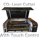
Hi everybody, my name is Michiel and I am going to show you how to make an awesome looking laser engraver!
A couple of months ago, there was a CNC challenge here at instructables, while checking out the entries of that contest, I saw some pretty cool engraving machines and I thought: "Why shouldn't I make my own?". And so I did, but I didn't want to make someone else's project, I wanted to make my own. And so my story began... :)
This laser engraver uses a 1.8W 445nm laser module, of course, this is nothing compared to the industrial laser cutters who use lasers of (a lot) more than 50W. But this laser will do well for us. It can cut through paper and cardboard and it can engrave all kinds of wood. I haven't tested other materials yet, but I'm sure it can engrave many other materials. l will let you know! It has a large engraving surface of about 500x380mm.
Who can make this laser engraver? Everybody, if you are an engineer, a lawyer, a teacher or a student like me, you can build this thing! All you have to do is follow this instructable.
It took me about three months to design and build this engraving machine, including waiting for about a month for parts. I said three months, but, I'm only 16 years old, so I could only work in weekends.
++ As you may already know, this 'machine' uses a 1.8W laser with a wavelength of 445nm, the radiation of this laser is very dangerous for your eyes, even a reflection of it! So I strongly advise you to use safety goggles with the wavelength of the laser you use! ++

Step 1: Bill of Materials

You can't make a laser engraver without the parts, so I made a BOM-list with almost everything you need to make it. Almost everything in the BOM is bought from Aliexpress.com because it's cheap and it has free shipping for most items. Other parts like the threated rods and the wooden sheets were purchased at my local DIY company. I ordered the laser and the laser driver on ebay.
UPDATE: I've uploaded the BOM in two formats: one .pdf and one .xlsx since not everybody could open the BOM.
I tried to find the cheapest products for all the parts (shipping not included).


Step 2: Design


Well, It took me a lot of time before I came to this design, first I made a few others, but this one was truly the nicest design i've made (if i may :)). I have drawn all of the parts you need to make on my computer and I uploaded them somewhere in this step (go find them!). If there are missing a few dimensions on some of the drawings, it's because I will tell you later in this instructable or because it really doesn't matter :).
The whole machine is made of MDF sheets with a thickness of 18mm and 12mm.
I made this design also because it would be very easy to attach a Z-axis and a dremel rorary tool so you can convert it to a cnc router.
UPDATE: Do you want to make the parts with a cnc router? No problem! I've uploaded STL files of all the parts so you can easily make them with a laser cutter or cnc router.
**Sorry for the names of al the parts, I thought they would be better.
Of course, I could have made an other simpler design... But hey! Where's the fun of that!
This step in one sentence: Print the drawings! :)
Attachments
 Base Plate.pdf
- Electronics case back.pdf
- Electronics case control panel.pdf
- Electronics case door.pdf
- Electronics case front.pdf
- Electronics case Left side.pdf
- Electronics case Right side.pdf
- Electronics case top.pdf
- Work sheet.pdf
- X-Axis moving part.pdf
- X-Axis Nut support.pdf
- X-Axis shafts + motor support.pdf
- X-Axis shafts support.pdf
- Y-Axis moving part.pdf
- Y-Axis nut support.pdf
- Y-Axis side + motor.pdf
- Y-Axis side.pdf
- Base Plate.stl
- Electronics case back.stl
- Electronics case Control panel.stl
- Electronics case door.stl
- Electronics case front.stl
- Electronics case left side.stl
- Electronics case right side.stl
- Electronics case top.stl
- Work sheet.stl
- X-Axis moving part.stl
- X-Axis nut support.stl
- X-Axis shafts + motor support.stl
- X-Axis shafts support.stl
- Y-Axis moving part.stl
- Y-Axis nut support.stl
- Y-Axis side with motor.stl
- Y-Axis side.stl
- Arduino Laser Engraver.stl


Step 3: Make the Wooden Parts


When you have printed the drawings, draw them on your wooden sheets (the right ones!) and saw them out with a jigsaw. If you don't have a jigsaw, go ask one to your brother, neighbour, cousin, colleague, santa, or go fetch one in your local store. When all the parts are sawed in the right form, it's time to drill the holes.
- The electronics case front and top: These parts don't have a flat side, so I drawed the angle with a pencil on the other sides and used a dremel rotary tool with that sandy bandy thing on it, I don't really know the name of it. If you don't have a dremel yourself, please don't bother your friends again and buy your own dremel! Just kidding, a rotary tool is a very handy tool and you should really buy one.
- The X- and Y-Axis nut supports: These parts have a hexagonal hole in it so they can hold a nut. To make that hexagonal hole, you need to drill a hole with a diameter of 11 mm through the part. Next, put the threated rod in the hole and screw the nuts on both sides, take a pencil and draw the shape of the nut on the part. Remove the nut and the threated rod. Now, take again your dremel and with a little cutter thing on it (see images), cut out that hexagonal hole with a depth of 6 mm and put a nut in it. Have a look at the images, they show wat you need to do.
Step 4: Assemble Your Laser Engraver!


Now, you have all the parts you need to assemble it. The first thing I did here was mounting the door in the electronics case left side with a lock and a hinge (that's the easy part, so I did that first :p ). To assemble the electronics case I used a lot of those L-formed iron pieces with holes in it, I don't know what they're called in English but you'll know what I'm talking about when you see the pictures. If someone knows how to call them, please leave it in a comment, for now, I will just call them 'those things'.
UPDATE: Appearently these L-formed iron pieces with holes in it are called L-brackets. ;)
First, take again the left side of the electronics case and mount the front and the back of the electronics case on it with some of those things I talked about. I didn't use screws or nails to mount the top and the control panel, I just mounted some of those things again and laid the top and the control panel on those things, because when you want to put al the electronics in it, you won't have problems. Don't forget to mount some of those things to the right side of the electronics case, and mount it to the rest of the case.
Put the electronics case away for a second and take the base plate and the X-Axis shaft support pieces and mount them like you see I did in the pictures, make sure the X-Axis shaft + motor support is on the right side of the engraver. Now, you can mount the electronics case the same way you see in the pictures.
Take the two 700mm shafts, slide two linear bearing things on each shaft, put a shaft support on each end of each shaft and mount them to the engraver.
Now you should become something that looks like the 7th picture. If not? Go back a few steps and find out what you did wrong. If yes: keep up the good work!
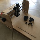
Put this half laser engraver away for a minute and take the X-Axis moving part and the Y-Axis shaft supports and mount the shaft supports to the X-Axis moving part with some nuts and bolts and attach the two X-Axis nut supports to it. Now, take the two 500mm shafts, slide one linear bearing thing on each shaft, put a shaft support on each end of each shaft and mount them to the engraver.
Mount the Y-Axis nut support to the Y-Axis moving part with nuts and bolts and attach it to the linear bearings with some bolts and attach the threated rods and the stepper motor.
Mount this whole thing to the other half of the engraver and attach the threated rods and the stepper motor.
Now you should become something that looks like the 11th picture.
I've also mounted a wooden piece in the electronics case to mount the stepper drivers.
I've attached the electronics case top, control panel and working sheet after I had put in the electronics, or you can just lay them on your engraver to admire your work and the magnificent design. :)
Step 5: Put in the Electronics


The only thing that's missing now are the electronics, the wires may look like a mess, but if you take your time and lay one wire at a time, it's a quick and easy step.
First, attach all the boards, power supply, relay, laser and control buttons (start, pause and stop) like in the fourth, the fifth and the sixth picture. Also, I used two fans I got from an old computer, these are necessary for the cooling of the laser and the stepper motor drivers.
Secondly, set the stepper drivers like I did in the third picture, these switches let the driver know what the current of your motors is and if you use microsteps. Wtih microsteps, the driver divides every step in multiple steps (the motor needs for example to turn four microsteps to have the effect of one normal step). I decided not to use the microsteps, because one normal step is for my engraver 0.0075mm.
Now, just print the first image and put one wire at a time and note on the printed image which wire you've done and which not. This picture uses other stepper motor drivers because the program I made it with doesn't support the driver I use.
Laser Driver: I didn't really knew what driver I needed to use for the laser, so I looked a little bit around here on instructables and I saw that FamousMods, an other author here on instructables, just used a LED driver from ebay in his instructable.
Stepper motor driver: The stepper motor driver says some weird things like EN-, EN+, CW-, CW+, CLK- and CLK+. You can combine EN-, CW- and CLK- and attach them with a wire to a GND-pin on your arduino. EN+ can go to pin 8. CW+ stans for direction and CLK+ stands for step pulse.
Limit switches: These switches make sure the engraver stops working when one of the axes pushes one of them, this is to prevent damage to the engraver in case something goes wrong. These switches are also used to find the home position of the engraver.
Step 6: Configure Grbl


The software is the only thing left now, so let's begin!
Go to this website and download the latest version of grbl (grbl-master), this is the software we use for our laser engraver.
You also need to download the latest version of arduino IDE.
When you've downloaded grbl, search for the config.h file in the folder named 'grbl' and replace that file with the file I uploaded here somewhere in this step.
When you've done this, open the arduino IDE and go to 'sketch' -> 'import library' -> 'add library' and select the folder named grbl. Select again 'import library' and click on 'grbl'. Now you should become something like the first picture.
Now press, while in the arduino IDE, ctrl+shift+M. This is the serial-monitor, set the baud rate (right bottom of the window) to 115200. You should see something like the second image now.
Press '$$', hit enter and you will see some settings, change them to this:
$0=10 (step pulse, usec)
$1=25 (step idle delay, msec)
$2=0 (step port invert mask:00000000)
$3=0 (dir port invert mask:00000000)
$4=0 (step enable invert, bool)
$5=0 (limit pins invert, bool)
$6=0 (probe pin invert, bool)
$10=3 (status report mask:00000011)
$11=0.010 (junction deviation, mm)
$12=0.002 (arc tolerance, mm)
$13=0 (report inches, bool)
$20=1 (soft limits, bool)
$21=0 (hard limits, bool)
$22=1 (homing cycle, bool)
$23=3 (homing dir invert mask:00000011)
$24=50.000 (homing feed, mm/min)
$25=500.000 (homing seek, mm/min)
$26=244 (homing debounce, msec)
$27=3.000 (homing pull-off, mm)
$100=133.333 (x, step/mm)
$101=133.333 (y, step/mm)
$102=250.000 (z, step/mm)
$110=500.000 (x max rate, mm/min)
$111=500.000 (y max rate, mm/min)
$112=500.000 (z max rate, mm/min)
$120=10.000 (x accel, mm/sec^2)
$121=10.000 (y accel, mm/sec^2)
$122=10.000 (z accel, mm/sec^2)
$130=500.000 (x max travel, mm)
$131=400.000 (y max travel, mm)
$132=200.000 (z max travel, mm)
And upload it to your arduino.
Step 7: Create and Send Gcodes


To let our laser engraver engrave something, we need to send it some codes, these codes are called gcodes. To create these codes, we will use a program called Inkscape and an extension for it.
To download inkscape, just go to this page and download the stable version 0.48.5 (!), this is very important, because the extension doesn't work in later versions.
Now, download the files I uploaded in this step and place them in the folder C:\Program Files (x86)\Inkscape\share\extensions. Now you can make some gcodes.
*NOTE: Before you make a file or start to engrave, note that the engraver will not colour the picture, you will only see the lines.
1. To create a gcode, first find a line drawing in google images and copy it in inkscape.
2. Select the image and go to Path -> Trace Bitmap and click on OK. Now the image looks a lot sharper (see picture 3). Delete the old image.
3. Choose how large it needs to be.
4. Go to the tab Extensions -> Laser engraver -> Laser. Set the speed, the name and the location of your file and click on OK.
Now all you need to do is send the file to your engraver. To do that , you need to download GRBL controller 3.0
UPDATE: I've seen that GRBL controller 3.0 gives an error when you try to download it, so I have found a good alternative for it named gcodesender.
Before you can send the file to your engraver, you need to let the engraver find his zero position. Click on unlock grbl and send $h to the engraver, after that, click on zero position.
Before you can engrave now, you need to focus the laser, to do that, just click on 'spindle on' and take a little screwdriver and turn the left POT so the laser only has 0.1 amps. Now you can turn the lens until the laser is focussed in one little point. Turn the POT back to 1 - 1.6 amps. Don't give it more than two amps or you will damage the laser!! *experience :)
Now, you can select the file and start to engrave.
If you notice the engraved picture is upside down, just switch the wires of one coil of of the stepper motors.
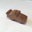
Step 8: Go Print Some Things!!


Congratulations! You've now made your own laser engraver! The only thing left is to engrave some things, here you have got some examples I've made with my engraver.
If you made this project, don't forget to send me a picture of it, I'd love to see yours
and if you have any questions, you can always send me a mail or leave a comment.
Thanks for reading my instructable!! ;)

Second Prize in the
Full Spectrum Laser Contest 2016

First Prize in the
Arduino All The Things! Contest

Participated in the
Plywood Contest


