

Introduction: Arduino Laser Show (adapted From NothingLabs' Instructable)

Most of this project was directly adapted from the excellent Arduino Laser Show with Full X-Y Control by Rich Olson / nothinglabs.
About me: I'm Joseph Long, a physics student at Pomona College in Claremont, CA. This was made as my final project for our electronics class. I owe a great deal of thanks to my professor, Dr. Dwight Whitaker; our machinist, Glenn Flohr; our electrician, Tony Grigsby; our TA, Jonathan Raiman; Dr. Kwok; and all of my classmates.
Step 1: The Big Idea

Laser projectors are devices that can change the position of a projected laser 'point' very quickly to draw out pre-programmed shapes. In the big, expensive world of professional projectors, this is accomplished not (as I had thought) by moving the laser itself, but by precisely rotating mirrors to change its deflection. The components used to precisely position the mirrors are called "galvos", and are not too different from the galvanometers (i.e. volt meters) you may have encountered in your high school physics class.
Unfortunately, procuring galvos can be really expensive (especially getting just two for a project)! Instead, we're going to use regular old speakers to move our mirrors. And we're going to use the Arduino to adjust the speakers so fast that they'll create the kind of persistent image we want.
Step 2: Parts List  Electronics
Before you embark on your journey into Arduino-powered laser magic, you will need the following electronic components.
Arduino board – I used the Arduino Uno with the code provided in the NothingLabs instructable successfully. Runs about $30 at stores like AdaFruit Industries.
Pocket laser pointer – You'll want one of the ones that uses 3x1.5 V cell batteries (~4.5 V). These usually draw 30-40 mA, which means the Arduino can power them off of a digital out. (Oddly enough, this part gave me more trouble than all the rest. I might recommend getting a laser diode and lens assembly from somewhere like SparkFun. However, if cheap is what you're going for, it doesn't get much cheaper than $1 laser pointers.)
12 V / 3 A power supply – Note: you may need more than 3 Amps, depending on your speakers. (I did.) I used a PC ATX power supply, which will happily supply up to 17 Amps (!).
2 x 8 Ohm, 20 Watt non-inductive resistors – Sometimes called 'power resistors' or, occasionally, 'sandbars'. Available at Radio Shack - Catalog # 271-120
2 x (approx.) 100 Ohm resistors (any power rating) – These just serve to limit the current coming from your Arduino into the transistors. Close to 100 Ohms is fine.
2 x TIP120 Darlington transistors – Let the Arduino switch a larger current to the speakers. (Available at Radio Shack - Catalog #: 276-2068)
2 x TO-220 Heat sinks (for Transistors) – These get quite toasty. Optionally apply thermal compound to improve heat dissipation. (Available at Radio Shack - Catalog #: 276-1363)
2 x 470uF 35V Radial-lead electrolytic capacitor – Available at Radio Shack - Catalog #: 272-1030
2 x Alligator clips – For connecting to the laser pointer's battery compartment.
22 Gauge solid core hookup wire – For connecting the Arduino's headers to the rest of the circuit.
20 Gauge or thicker hookup wire – For delivering power to the speakers ("speaker wire" will also work here)
(optional) Perforated circuit board, cut to size – to keep components organized
2 x 4-6" Speakers – I used two "Peerless India W5-KA538A-SH 5.25" Shielded Woofer 4 Ohm" speakers ($5 each from Parts Express). Since I don't fully comprehend all the speaker-purchasing advice from NothingLabs, I'll just link to it.
Step 3: Parts List  Hardware
Mirror – Enough to cut two 1.5" square pieces. (If you can find it, using 'front mirrored' glass will be better, since you will not get refracted light from the glass.)
Small pieces of wood (0.5" x 0.5" x 1" or so) – Used as standoffs to keep the pivot from sitting too close to the cone (possible substitute: LEGO bricks)
2 x 1/8" Aluminum rod, cut to diameter of speaker – Used to pivot the mirrors (possible substitute: bamboo shish kebab skewer)
(optional) Plywood project board (18"x24") – Good for keeping everything in the same relative positions once it's all set up
(optional) 2 x Drinking straw (or other sleeve for aluminum rod) – Used to improve range of motion for mirrors
Note on mounting hardware:
Mounting your galvos such that they point at each other (and your projection surface) satisfactorily is more of an art than a science. I had the resources of my college's machine shop (and resident machinist; thanks Glenn!), so I was able to procure a sheet metal plate, some angled blocks of wood to mount it on, some metal "pipe tape" to secure another speaker, etc.
As long as your speakers are aimed correctly, and you're satisfied with their mounting, it doesn't really matter how it's done, so I won't reproduce a full parts list here.
Step 4: Parts List  Tools
Not all of these tools are essential, but they can make your job much easier (and your finished product nicer).
Soldering iron – Don't leave home without it!
Solder – No special size necessary
Solder sucker – Absurdly useful when you've got to undo your mistakes
Digital multimeter – Useful for figuring out what your mistakes are in the first place
Hot glue, epoxy, and/or contact cement – You'll need at least one of these to affix mirrors and pivots to your speaker.
Drill with electric screwdriver – useful for the mounting hardware
Heatshrink tubing and heat gun – hide your ugly solder joints
Electrical tape – for when you run out of heatshrink tubing
Step 5: Mounting the Mirrors

A note on cutting the mirrors: If the mirror comes with a cardboard or plastic backing that can be removed, remove it. If you have access to a glass cutting tool, use that to score and break out two 1.5" square pieces for mounting. If not, acrylic camping mirrors can be cut by more readily available tools (like a bandsaw or a hacksaw).
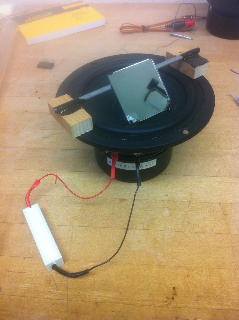
Before you begin mounting the mirrors, check that your standoffs are tall enough to let your mirror segment reach both the speaker cone and the pivot sitting across the speaker.
First, affix your standoffs to the rim of the speaker (mine had convenient holes meant for mounting the speaker that I used to attach wooden standoffs). Then use epoxy, hot glue, or a mounting bracket to attach the pivot rod to the top of the standoffs, roughly centered over the speaker cone.
Now it's time to attach the mirrors.Using a hot glue gun, attach the back of the mirror to the pivot rod (or straw sleeve, if applicable). Then, affix the mirror at two corners to the speaker cone as shown.
Step 6: Attaching the Power Resistors
The 8 Ohm, 20 Watt power resistors go in parallel with the speakers. They don't have to be oriented a certain way, so you can just attach one end to the + terminal and one to the – terminal on each speaker, as shown in this picture.
Step 7: Laying Out the Circuit


However, I wanted to clean up things a little bit, so I opted for a perforated board (shown) with the (non-speaker) components for the X and Y galvos peacefully coexisting. (A breadboard or PCB probably wouldn't work for this case, since the traces would have to carry more than 3 Amps!)
The secondary pictures show the components for driving one of the two speakers: a TIP120 Darlington transistor, a filtering capacitor that cleans up the power from your power supply, and a 100 Ohm resistor to limit current draw from the Arduino. Repeat for the other galvo.
(For more detailed information about each connection, the original Instructable can't be beat. I did not document my circuit building quite as extensively.)
Step 8: Connecting the Speakers to the Control Circuit
When you have your circuit set up, it's time to connect the speakers! Connect the negative terminals on your speakers together with two lengths of 20 Gauge or larger hookup wire, meeting in the middle. The middle is where you will attach the wire to your power supply's +12 V. Be sure to use plenty of wire (1.5 to 2 feet!) to ensure you'll have plenty of slack for positioning the speakers.
Connect the positive terminal of each speaker to the wire running to the collector lead on the corresponding TIP120 transistor.
Step 9: Hooking Up Your Laser
If you're using a cheap laser pointer, the outer casing is usually the positive end of the laser circuit, and the spring that the batteries rest on is usually negative. Check the signs on your laser's batteries to make sure, as not all laser pointers will have protection against trying to run them in reverse-biased mode (which could break them).
Connect to the casing and the spring with two wires with alligator clips, and keep track of which is positive and which is negative.
If you have a diode and lens assembly, you should have a positive and negative wire out of it.
Take the positive end and connect it to a length of 22 gauge hookup wire which will fit in the pin 5 header on the Arduino. Do the same for the negative end, but connect it to one of the GND pin headers on the Arduino.
Pin 5 will be used to switch the laser on and off from the Arduino code. If you're not sure your laser is working, you can move the positive end from pin 5 to the +5 V header on the Arduino to test it (it should turn on).
Step 10: Connecting Everything to Power


I originally attempted this project with a lab power supply rated for 3 Amps at 12 Volts, but the components were drawing more current than that and I was forced to improvise. The short version of this step, for those with an adequate power supply, is to connect +12 V to the speakers' negative terminal and the positive end of the power filtering caps. Connect the ground lead of your power supply to the Arduino's ground if you are not powering the Arduino with the same supply.
It turns out that the power supplies from desktop computers make very good DC power supplies that can deliver a lot of current. I used a compact ATX power supply from a discarded Dell desktop that was rated for up to 17 Amps at +12 Volts. (Way more than you should need!)
The first step in adapting an ATX power supply for this purpose is to cut off the connectors coming out of it so you can solder to the wires directly. (I put little bits of electrical tape over all the ends for safety.)
There should be one green wire: connect this directly to a black (ground) wire. This is the DC power switch for the supply, so if you wanted to you could wire in a switch here rather than making the PSU think it's always on.
I had heard (but have not tested) that these power supplies need a minimum load to turn on. Since there will be points in the laser show where next to no current is being drawn, I connected an auto tail light bulb from one of the red (+5 V) wires to one of the black (ground) wires. A power resistor would also work; see other ATX power supply hack guides for more info.
There should be two or more yellow (+12 V) wires. Use one of these to power the Arduino. I connected a yellow (+12 V) and black (ground) wire to a 2.1 mm center-positive plug for easy connection to the Arduino. You can also connect them directly to the Vin and GND headers.
The other yellow (+12 V) wire should be connected to the negative terminals on the speakers (see the annotated version of the perforated circuit board image for more details). Take another black (ground) wire and connect it to the negative sides of the power filtering caps.
To recap: red and black for the minimum load bulb (or resistor), yellow and black for Arduino, and yellow and black for the negative terminals of the speakers and the negative sides of the capacitors, respectively.
Step 11: Aim Your Lasers

Now it's time to get your mirrors pointing at each other, and your laser pointing at the mirrors. (You may want to hook up your Arduino via USB and connect your laser to +5 V at this stage for ease of aiming.) This may be the hardest step in the whole instructable! Since I cannot really explain the configuration without effectively copying the NothingLabs instructable, I'll reproduce their explanation here.
"The Y galvo should be positioned with its mirror pivot running horizontally, and the mirror oriented down.
The X galvo should be positioned with its mirror pivot running vertically, and the mirror oriented towards your left.
The laser should be pointed at the mirror of the Y galvo.
The Y galvo should be angled so the laser bounces of its mirror onto the X galvo's mirror.
The X galvo's mirror should be pointed toward where you want the laser show to project."
If my image isn't clear enough, I recommend checking out theirs as well.
Step 12: Upload, Adjust, and Enjoy
Upload the laser show code (attached to this step) to your Arduino, switch on your power supply, and see where your alignment is off. If you are having trouble aligning the lasers, I recommend replacing the body of the loop() function with a routine to draw a square. The following code attempts to draw a square at the boundary of the drawable area of the projection.
void loop() {
laser_on();
sendto(1,1);
sendto(1,255);
sendto(255,255);
sendto(255,1);
sendto(1,1);
laser_off();
}
In my tests, I noticed that the far corner of the square was not drawing correctly, which was evidence of insufficient power to deflect both mirrors fully. I had to adapt a power supply (as detailed in previous steps) to deliver sufficient current. (If you're using a PC ATX power supply, you shouldn't have this problem!)
The attached code is from the instructable by NothingLabs, redistributed under CC-BY-SA with credit to Rich Olson. It hasn't been changed recently as of this writing (5/3/2012), but you should also check this page to see if there are any bugfixes.
Once you have everything set up, play with the code to draw new and fabulous things!
Thanks for reading!


