

Introduction: Arduino Lens Controller - Synchronized Zoom/Focus With Wii Classic Controller


The design that I eventually implemented has a number of advanced features:
- 2 joysticks provide continuously-variable speed lens control. Moving the right stick forward and back controls synchronized zoom and focus, and moving the left stick side to side controls just focus. The implementation of speed control also helps keep the servo noise down to acceptable levels.
- There are 6 programmable "goto" zoom/focus settings that can be programmed on the fly from the Wii Classic, and that will move the zoom and focus to the desired position just by pushing a button (left shoulder for widest zoom, right shoulder for most zoom, and a, b, x and y for any zoom/focus position).
- The maximum lens movement settings can also be programmed on the fly to ensure that the servos don't try to rotate beyond the limits of the lens's zoom and focus positions.
- D-pad provides single degree movements of zoom (up and down pad) and focus (left and right pad) to make precise adjustments for critical focus/zoom.
Here's a demonstration of how the synchronized zoom - focus works on my GH2 with a Nikon 28 - 85mm zoom lens:
In this instructable I'll cover the basics of how to build your own version of this controller, including the Arduino code and instructions for mounting the servos to a rail-based camera rig. I'll mention how I built my rig, but since I'm not really happy with it, I won't go into detailed steps on that and will leave it to you to figure out your own solution based on the pictures of my rig and some notes about how I made it.
This was my first attempt at building something with Arduino, though I've had some programming experience so it wasn't too difficult for me to learn the basics of Arduino code. However, if you want to tackle this project and you haven't already gained familiarity with setting up and programming an Arduino, I recommend that you go through the tutorials on the Arduino site, especially those for Servos. http://arduino.cc/en/Tutorial/HomePage
Step 1: Getting Started: Tools and Materials

You can complete the electronics for this project with just some wire strippers and a soldering iron. But to make the servo mounting arms it helps to have access to a bandsaw and a drill press (though careful work with a hand drill can negate the need for the latter). I also used a tablesaw to cut the sheet plastic and a table-mounted router with a 1/2 diameter core-box bit to cut the grooves in the plastic to match the rails on my home-made camera rail system.
Here is a list of the major supplies you'll need to complete this project, but please go through the whole instructable before buying anything so that you'll understand what to purchase in order to fit your own needs.
- Arduino or Arduino clone (I used a Seeeduino because it was a little cheaper than the Arduiino and provides the same functionality).
- Wii Classic Controller. I bought mine from eBay for around $10 shipped.
- Wiichuck Adapter (a little circuit board that plugs into your Wii Classic so you don't have to cut the cable). I got this from FunGizmos for $4: http://store.fungizmos.com/items/212
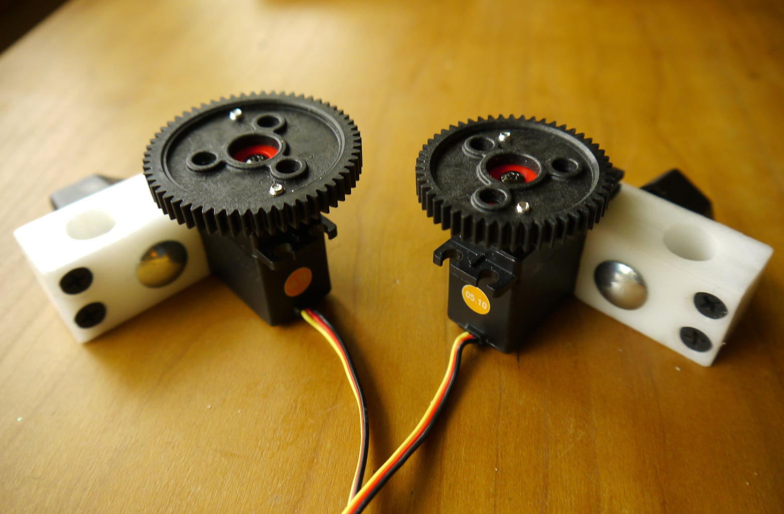
- 2 standard sized hobby servos with nylon gears and ball bearings. The nylon gears are quieter and the ball bearings provide better support for the shaft when handling the load of stiffer zoom lenses. I bought some surplus servos from a local RC store for $5 each, but am replacing them with 360 degree digital servos that should be even quieter and more accurate, and those cost me $20 each from eBay.
- 2 lens gears to mount on your lens's zoom and focus rings. I used the flexible ones that I found on eBay for $10 each, and made my own spacer rings to provide better resolution and a bit more mechanical advantage for the servos. You can also spend about twice as much and get lens gear rings that have built-in spacers, and these are also available on eBay. just search for "lens gear follow focus".
- 2 Drive gears to mount on the servos to drive the lens gears. These need to be 32p or mod .8 gear pitch (which is the standard pitch for lens gears). I fashioned my own drive gears by fitting some $4 RC spur gears to the original servo control arms, but that required some work on a mini lathe that not everyone has. A better option would be to buy the servo-mountable gears from Servo City for just a few dollars more: http://www.servocity.com/html/32_pitch_hitec_servo_gears.html. While you're ordering those, you'll save yourself some trouble is you also buy a pair of male servo leads to make it easier to connect your servos to your Arduino and to swap servos if the need arises.
- 1/2 inch thick sheet plastic or 3/4" thick aluminum to make the servo mounts. I used an old plastic cutting board, but if you do, make sure that it's the harder ridgid kind (you should not be able to dent the surface at all with your thumbnail). The softer kind is UHMW and will not machine well enough for this purpose.
- knobs and matching carriage bolts for clamping the servo mounts to the rails.
Step 2: Choosing Gears and Servos for Your Lenses
Before you purchase your servos or gears, you need to understand some things about servos. Servos have a limited range of motion (typically 180), so if you want to be able to control your lens throughout its entire zoom and focus range, you need to do a little calculation based on your lens's ring movement and the diameter of the lens gear that the servo will be driving. I think it's best to just go through the process that I went through, so you can follow the same approach for your own system's needs.
My lens's focus and zoom rings move about 90 degrees from end to end, and with the spacers and lens gear the total diameter of the gear being driven by the servo is 4.25 inches. I used a circumference calculator from this web site (http://math.about.com/library/blcirclecalculator.htm) to get a circumference of 13.35 inches. Since 90 degrees is 1/4 of 360, I can calculate that my servo needs to provide about 3.4 inches of travel (13.35 / 4). I used standard 180 degree servos, so I know that the circumference of my servo drive gears had to be at least 6.8 inches (180 degrees is half of 360, so my servos will only be able to provide movement that is half the total circumference of the servo drive gears). Using the circumference calculator again, I know that I need gears that are at least 2.2 inches diameter. I actually ended up using a slightly smaller lens gear because I don't need the full range of focus motion and I wanted to have a little finer control of focus since that is more critical than zoom for me. This is another consideration to keep in mind - the closer you are to 1:1 between drive gear and lens gear, the less resolution you have. For example, in my setup a 1 degree servo step = 1/2 degree lens step, but if my drive gear diameter was equal to the lens gear the lens would move 1 degree for each servo degree. You also need more servo torque for a 1:1 drive:lens ratio that you do for a 1:2 drive:lens ratio.
You should also know that there is another variable that you can introduce - servo rotation. My servo control code is written for standard servos that rotate 180 degrees, but I've ordered a pair of digital servos that rotate 360 degrees and that will allow my controller to handle lenses that require more travel. You can get servos that rotate up to 3 turns, which should be enough to handle most lenses while maintaining low drive to lens gear ratios. Of course you'll have to make some minor changes to the code to handle the increased degree range, but it should be pretty straightforward. If you want full turn or multi-turn servos, search for "winch servo" on eBay.
Step 3: Prepare Your Arduino (or Clone)

Once you have your Arduino (or equivalent), your Wiichuck connector, your servos and leads, and your Wii Classic controller, you're ready to start putting things together and to load the code onto your Arduino. Here's the outline: wire the Wiichuck connector and servo leads so you can start testing everything together (that step requires some soldering). Once you have things connected, set up the Arduino IDE on your computer, plug in your Arduino, and start loading the libraries and examples you need. Then the fun starts.
Wiring the WiiChuck Adapter:
This part is pretty easy, if you don't do what I did and lose the little 4 pin header that comes with it. You just solder the header in place, then plug it into the Arduino as illustrated in the image on the FunGizmos web site. To connect your Classic controller, just make sure that the indentation on the controller plug lines up with the "nc" on the Wiichuck adapter.
Wiring the Servos:
I originally purchased a motor controller board because I first tried to build this project with stepper motors rather than servos (because I thought they wold be quieter, which turned out to be quite wrongheaded). The board has 2 hobby servo connectors, so I didn't have to do any soldering to connect my servos. But the process is for wiring them straightforward: you simply connect the power leads of both servos (black is negative, red is positive) to ground and VCC of your board. You have several locations from which you can choose. Then connect one of the signal (yellow) wires of one servo to pin 9, and the other to pin 10. These are the default PWM pins that provide default pulse width modulation outputs that are required to tell the servo how far to turn.
Once you're done with the wiring, you can connect everything together, connect your Arduino to your computer via the USB cable, and start loading code.
Step 4: Program Your Board: Get the Libraries and My Code and Start Playing
Before you load the code that I wrote for my lens controller, you need to get the Arduino IDE set up on your computer and load the libraries that you need. The Servo control library is included with the Arduino IDE, so you don't need to do anything for that. However, my code also uses a user-contributed Wii Classic Controller library that is available on the Arduino playground. http://arduino.cc/playground/Main/WiiClassicController10
You can follow the steps on the page to add this to your library, or just download the zip file that I've attached and unzip it into your Arduino libraries folder. Mine is in this path:
..\Documents\Arduino\arduino-1.0\libraries\
I created a folder called MiconoWiiClassic in the \libararies folder, and saved the "WiiClassic.h" file in that folder. You can just unzip the MiconoWiiClassic.zip file that I've included here to your Arduino-1.9\libraries folder.
UPDATES:
1) Since first posting this Instructable, I've figured out how to double the resolution of the servos, which makes them smoother and more accurate. I did this by tweaking the Servos library that is installed by Arduino. You can either tweak the library yourself, or you can download the Servo.zip file and extract the Servo.cpp file into your ..\Arduino\arduino-1.0\libraries\Servo folder and overwrite the Servo.cpp file that's there. If you want to tweak the file yourself, you can just open the file from your library in Notepad, and replace all instances of "180" with "360". If you downloaded my sketch before I made this update, you should re-download FocusController_gp.zip and extract it to your sketch folder. It will add focus_zoom_controller_servo_final_2xresolution.ino to that folder.
2) After you unzip the files you need to change one thing in the WiiClassic.h file in order to make the library work as expected with my code.The WiiClassic.h library contains a DEFINE_ON_HOLD feature that must be uncommented in order to ensure that the button presses are reported just once. To uncomment this, you have to open the ..\arduino-1.0\libraries\MiconoWiiClassic\WiiClassic.h file in Notepad and change the following line:
//#define REPORT_ON_HOLD
to
#define REPORT_ON_HOLD
If you don't do this, you will notice that the D-pad button presses will keep moving the servos as you hold the button, whereas it should only move the servo one step per press. This error may also cause strange behavior from other button presses.
3) If you're plugging the WiiChuck adapter in to Analog pins 2,3,4 and 5, you need to configure 2 and 3 as ground and power, by adding the following to the setup section of your code (thanks to Phillip James for catching this ommision)
"pinMode(16, OUTPUT);" Sets digital 16 pin (aka Analog 2) as ground pin
"digitalWrite(16, LOW);"
"pinMode(17, OUTPUT);" Sets digital 17 pin (aka Analog 3) as +5V pin
"digitalWrite(17, HIGH);"
Once you have that library in place, you can also download my project code and unzip it to your main Arduino folder, and the next time you launch the Arduino IDE, my projects will show up in your Sketchbook folder. My Arduino folder is in my documents folder, like this:
..\Documents\Arduino\

Step 5: Test Things Out: Wii Classic Controller
With the electronic parts connected and your code in place, it's time to start testing things out and tweaking the code, if necessary. Start by loading the WiiClassicTestValues sketch from your Sketchbook (File > Sketchbook > WiiClassicTestValues). Before loading it onto your board, compile it to make sure that you've installed the WiiClassic.h library properly (you should also be able to see it in your libraries list (Sketch > Import Library). If it compiles properly, load it onto your board.
The program outputs the value of each of your sticks on the Wii Classic to the Serial Monitor, so you'll need to open the Serial Monitor (Tools > Serial Monitor). Let the controller run with the sticks at rest to see what the values are at the center positions, then methodically push both sticks all the way forward for a few seconds, then all the way down, then all the way left, then all the way right. Once you've done that, you can turn Autoscrolling off in the monitor window and copy the results to Notepad and save the file for further review. You're now ready to ensure that the controller code is calibrated to your Wii Classic Controller.
Step 6: Load the Lens Controller Code and Adjust for Your Wii Controller
Now you can load the controller code and ensure that the expected controller values match your Wii Classic Controller. Start by loading my controller sketch from File > Sketchbook > focus_zoom_controller_final.
Once it's loaded, scroll to line 101 of the code to see the settings for the controller stick values, shown below:
// the right stick has 1/2 the resolution of the left - these values may vary from one
// controller to another, so you'll need to run a test program to discern the values of
// each stick position
int yCenterRight = 15;
int yMinRight = 2;
int yMaxRight = 28;
int xCenterRight = 15;
int xMinRight = 3;
int xMaxRight = 28;
int centerOffsetRight = 3;
int endOffsetRight = 0;
int yCenterLeft = 32;
int yMinLeft = 6;
int yMaxLeft = 55;
int xCenterLeft = 31;
int xMinLeft = 6;
int xMaxLeft = 55;
int centerOffsetLeft = 6;
int endOffsetLeft = 0;
Check these values against the read out from your controller, and change any values as necessary. Make sure you save your changes.
Step 7:
It's time to test out the code with your servos. In my code I have the Zoom servo attached to pin 9 of the Arduino, and the Focus servo attached to pin 10. You can easily change that in the code by changing the numbers here:
void setup() {
Serial.begin(9600); // set up Serial library at 9600 bps
//attach servos and set them to initial positions for mounting the servos to the lens
zoomServo.attach(9);
focusServo.attach(10);
Once that is done and your servos are connected, plug your board into the USB port on your computer and download the code to your board. When it's done downloading and booting, the Zoom servo will move to 180 degrees and the Focus servo will move to 0. You can now start playing with the sticks and buttons to see what happens, and can try programming the various servo positions and the focus ratio. Some of the buttons have default values, but you can program any button by pressing, HOME, then the button and the program will remember the setting until the board is reset or powered off.
Once you're satisfied that the controller is working correctly to move the servos, you can grab your camera and lens and assess whether the servo directions for the stick movements are correct. Pushing the right stick forward should turn the servo in the correct direction to zoom the lens, and pulling it back should do the opposite. At the same time it should move the focus in the direction that is needed to keep the camera in focus when the zoom is moved. I have mine set up so that when I zoom in (push the right stick forward), I have to move the focus stick to the right to correct the focus, and when I zoom out (pull the right stick back), I have to move the focus stick to the left to correct the focus. This seemed like the most intuitive arrangement.
By setting the servos next to your camera and lens in the way you plan to mount them on the camera rig, you can tell whether they are moving in the right direction given how your lens moves. If they don't, there are instructions in the code on how to change the direction of servo movement relative to each stick movement. I have future plans to hack the Servo library to make this easier, but for now it's not as easy as flipping a switch, but it's also not overly complicated.
Step 8: Put It Together for a Real Test


Here's where it really gets fun. Once your satisfied that you have the servos moving in the right direction for your camera, there's really no reason not to mount everything an see how it works with your camera and lens. You can make enclosures and add switches, power connectors, and pretty lights once everything is working to your satisfaction, but there's really no point in doing that until you see whether your setup is able to drive your lens the way you want. I did this with several iterations of my project, including a stepper-based version that was a complete disaster and caused me to change course and switch to servos. The idea is to fail fast, before you've committed too much work on a final product that still needs tweaking.
Start by mounting the servo drive gears and the lens gears. This is all pretty straightforward, but if you find that your lens gear is slipping at all (as mine did), it may help to know that you can increase the grip of anything with the rubber backing that's easily peeled off the back of a cheap, thin mousepad. The same stuff can also be used to deaden noise from the servos. Along those lines, adding some plastic-safe grease to the servo gearbox can also help reduce the servo noise. I used fishing reel grease that is designated as plastic safe, and it really quieted my zoom servo.
If you don't have a rail system, you'll need to fashion one by either following what I did (I'll let the picture guide you) or find an even better design on the web. My rig was put together quickly for testing purposes, and I plan to replace the cobbled-together design with something more attractive, rigid, and easy to adjust. My rails are 1/2 diameter carbon ski poles that I snagged from Goodwill for $4 (Goode brand are not tapered, so they worked well for this). The rail holder is made from a 1/2" thick hard plastic cutting board that I sawed into a 2-1/2 inch wide by 6" long strip. To create the rail "holes" I routed two 1/4" deep by 1/2" diameter grooves with a core box bit mounted in a router table and guided by a small fence. I now wish I had made thiis whole thing wider, but I wanted to keep it narrow so I could still get to my battery door without dismounting the camera from the rails. I then cut the piece in 2 lengthwise, mounted a spacer block of baltic birch plywood to one end with some wood screws, and then drilled a couple of 1.4" holes in it for attaching it to the camera and the Manfrotto quick release plate.
Once you have a a rail rig, you can fashion some servo mounting blocks to fit your rails. I also made mine from some hard plastic cutting board scrap that I routed on my router table. I screwed one end together with some small drywall screws, and drilled a 1.4" whole on the other side of the rail hole to hold a carriage bolt. A small knob allows me to tighten the mouting block for a pretty snug fit on the rails. Once I was sure everything fit OK, I drilled tiny pilot holes to fit the servo mounting screws that came with my servos, and fastened the servos in place. Note that with this arrangement the servo is only fastened at the front edge, so be careful where you exert pressure when mounting the servo and block assembly on the rails.
Step 9: Give It a Test Run

Program your controller for your lens (these instructions are also in the Arduino code)
After your board boots up and the servos have stopped moving, move the lens zoom ring to that it is at the max setting that corresponds to the servo position. When my controller starts up my zoom servo moves to the widest zoom position, so that's where I move the lens before I engage the zoom servo. After I've moved the lens, I swing the servo into position so the drive gear just engages the lens gear (if put too much pressure on the lens, you may cause it to stick and you won't get as smooth of movement). I then program this as the widest zoom setting by pressing "Home", then "Left Shoulder " on the Wii Classic Controller. I then use the right stick to zoom in until the camera hits its zoom limit, and use the pad to back off a degree or two. I then program this max zoom position by pressing "Home", then "Right Shoulder" to program the maximum zoom setting of the lens.
I repeat a similar procedure for the focus servo, but program the right most and left most focus servo settings using the "Right Z" and "Left Z" buttons.
Once these limits are set, it's time to power up your camera, pick a subject and set the focus for the widest and closest zoom settings. It doesn't matter where you start, but I usually go max zoom (just press the right Shoulder button to automatically go there). I then use the left stick and left-right D-Pad to get the focus right, then press "Home" then "+" to set the focus for Max Zoom. Next zoom your lens all the way out to the widest zoom and again, use the left stick and D-Pad to dial in the focu on your subject. Once it's good, press "Home" then "-" to set the focus at the Min Zoom (widest zoom) position. Each time you program either the "-" or "+" buttons, the code calculates the correct ratio to move the focus while zooming in order to keep your subject in focus as you zoom. You can tweak the focus at any time by using the left stick or the D-Pad, and until you re-program the "+" or "-" key the focus will always move in synchronization with the zoom movement when you use the right stick to zoom your lens. This is where the magic of my "contraption" (as my wife calls it) is.
You can also program the 4 (x, y, a, b) buttons with dedicated Zoom/Focus positions. Just move the zoom and focus to the desired position, then press "Home", and then the one of the buttons to program it for that position. If you move only the focus servo while programming each of these buttons, you can make your controller work like a follow focus with 4 preset focus positions that don't move the zoom lens at all.
Here's a video demonstrating this process with the controller mounted on my GH2 camera:
Step 10: Wrap It Up
When you're done playing and teaking and satisified that your own version of my controller will work for you, it's time to make it all permanent, pretty, and easy to mount and dismount. I'll let you figure that part out on your own (but hopefully you'll share your results with me). I have a number of tweaks to make on my controller before I finalize it, so I thought I'd share my plans here to get you thinking along the same lines.
Enclosure and Better Servo Mounts
I just haven't foudn the right enclosure yet, so I'd welcome sugestions here. I'll probably buy a smaller Arduino like a mini so I can keep things small and that will open up my options. I'm also going to rpelace the plastic servo mounts with machined aluminum mounts now that I know how well this thing works. I'm also going to upgrade the servos themselves.
Power Supply
Right now my controller runs off USB power by plugging my USB cord into an iPod charger. However, I have a spare external 9 volt DVD battery that can be charged while it's supplying power to by controller, and I like the idea of having battery only option so once I've found a suitable enclosure I'm going to wire the proper connector to the external poer pins on my board.
LED Indicators
It would be nice (and very easy to add an indicator for "program mode", so I have some LED's that will illuminate when the controller is in Program or Run mode.
Easy Servo Reversing
As I indicated earlier, it's a bit tedious to change the direction of the servo relative to the stick movements, so I've started working on hacking the Arduino servo library to accept a servo direction flag.
Memory for Lens Settings
It would also be nice to not have to reprogram the lens limit settings each time the controlle ris powere off, so I plan to add SD card based storage for each lens setting.
Step 11: Feedback and Follow Up


Another member. Steve Dray, has done a great job building a couple of his own versions of this rig, and has generously shared his wiring diagrams and pictures. I hope this inspires and helps others trying to build this project, especially since I've had limited time to answer questions. Steve was having some problems that he diagnosed as a poor power supply, so he built his own regulated supply, and included the schematic for that as well. I've managed to get by with my little cube ipod charger.
Thanks Steve!

Participated in the
Arduino Challenge


