

Introduction: Arduino Lie Detector


Hey everyone today I want to show you how to make an Arduino-controlled lie detector to see when your friends are lying to you :D or to measure the different responses that your bodies skingoes through depending onthe situation you are in or the emotions you are feeling and the coolest thing of all is that we can see all of theses things happen in real time in an Arduino graph.
Step 1: How It Works

Our skin is amazing! It provides a medium for us to experience the sense of touch, it keeps infections out and keeps innards in but I bet you didn't know that our skin changes conductivity depending on many different things one being our mood! It called Electrodermal activity (EDA) and there's a really interesting Wikipedia page you can read here. The basics are that our skin changes its conductivity depending on how we feel.
We start by connect our Arduino to the subject and then connect the Arduino to a computer with the graphing software (I'll go over this in detail later)
We have to start by asking the subject some easy questions we know they will answer truthfully like "what is your name" and "where do you live" to get a baseline and from there we can start asking questions that they may lie about, if they do they would probably feel nervous and then we can read the change in the base line that be established earlier if they lie :D
Step 2: Parts List


We are going to need a microcontroller to control the three LEDs and send the computer the data. In order for the computer receive the data from the microcontroller the microcontroller has to have a serial communication chip this means we can't use the Arduino pro mini or Adafruit trinket so when picking your microcontroller make sure it has a serial communication chip built in (USB communication chip)
Electronics components parts list
- Arduino Nano ( Get it here)
- Geen LED (Get it here)
- Red LED (Get it here)
- Orange LED (Get it here)
- resistor (10k) (Get it here)
- cables
Materials Needed
- Cardboard
- Tinfoil
- Velcro
- Hot Glue
Tools Needed
- Hot Glue Gun
- Soldering Iron
- Craft Knife
Step 3: Wiring
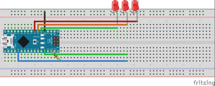
The wiring for this is pretty easy, we will start by connecting them in this order:
- Connect A long piece of cable to Arduino analog pin 0
- Connect the 2k resistor to ground and the the extended analog 0 pin
- Connect A long piece of cable to Arduinos 5 volt pin
- Connect the anode (long leg) of the green led to pin 2 and the cathode (short leg) to ground
- Connect the anode of the orange led to pin 3 and the cathode to ground
- Connect the anode of the red led to pin 4 and the cathode to ground
That's all the wiring for the Arduino, now we need a way to keep the sensor wires on our fingers we will cover this later.
Step 4: Software and Code
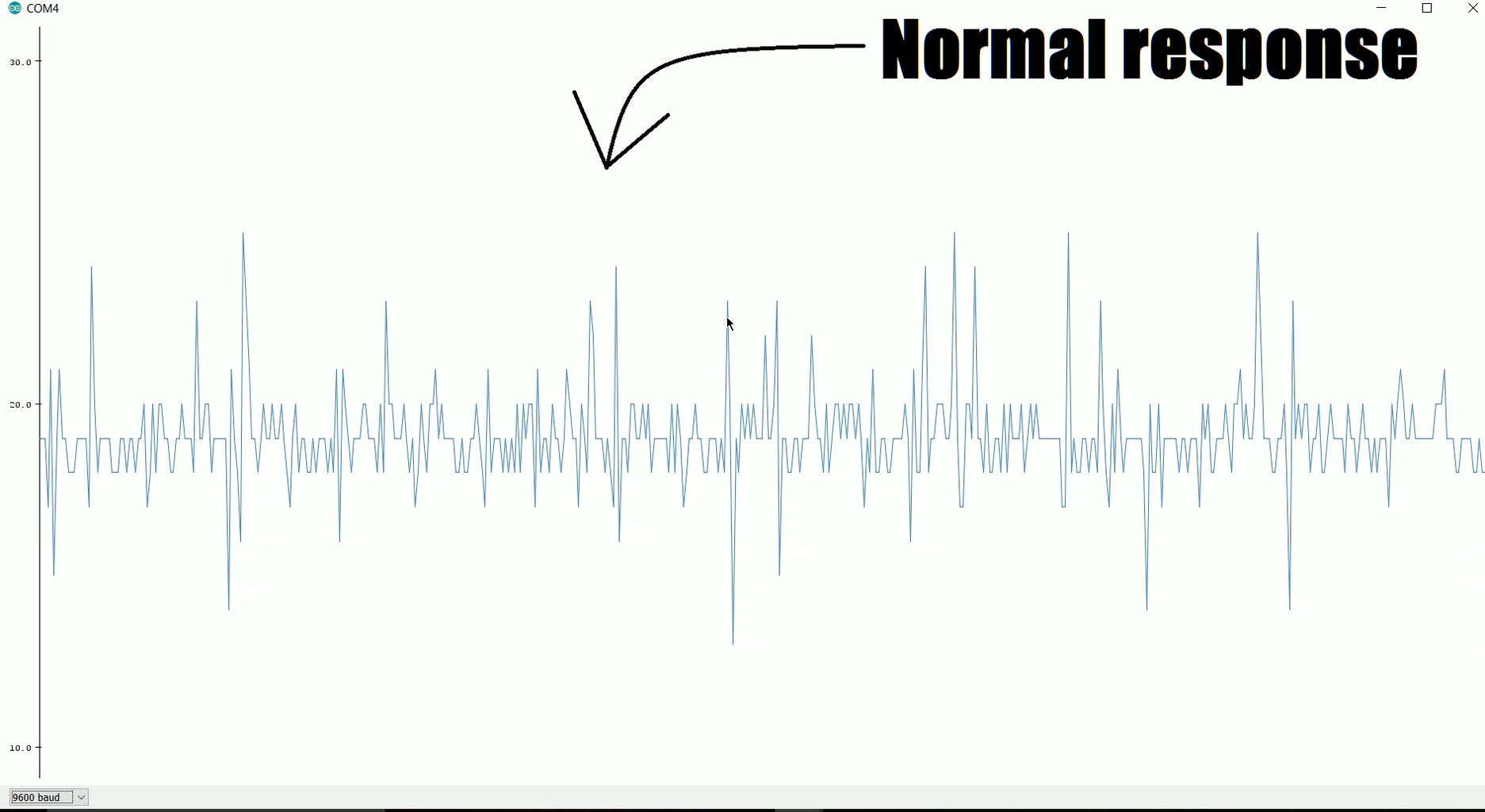
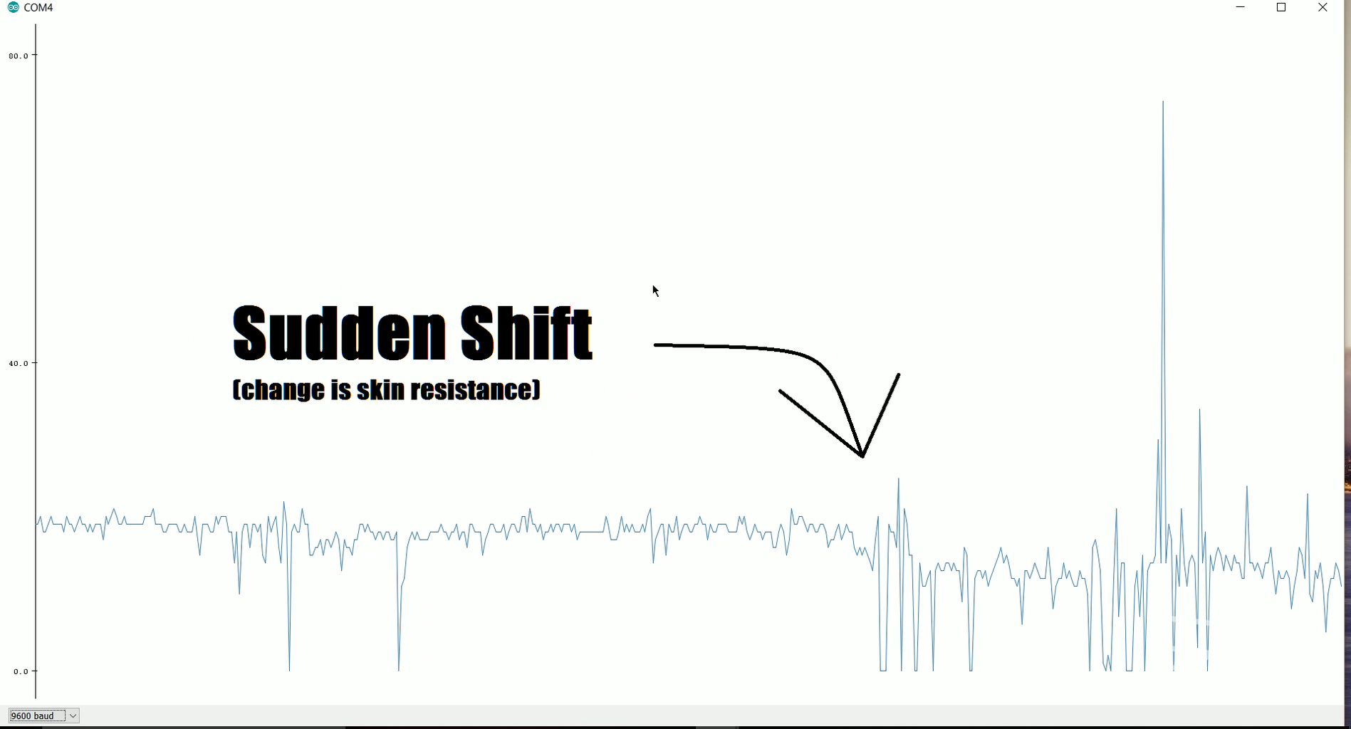
The main piece of software we are going use is the newest version on the Arduino IDE. The new update brings a new way to see the data being received from the Arduino, instead of being in text form from the serial monitor, it can now be displayed in a real time graph which will help us identify when the data changes its pattern (when someone lies)
To open the plotter open Arduino and navigate to the tools menu and you should see it there just below serial monitor.
Now the code for the micro controller download the attached file, open it and upload it to your board
Attachments

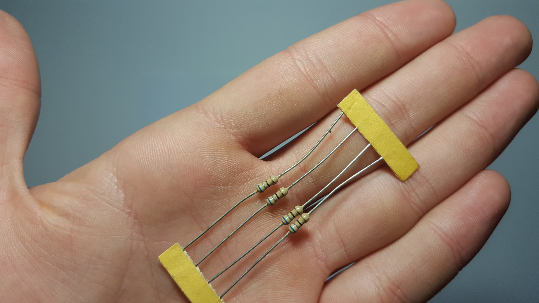
Step 5: Making the Finger Clips
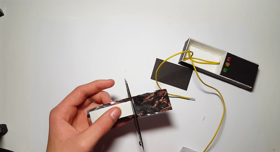

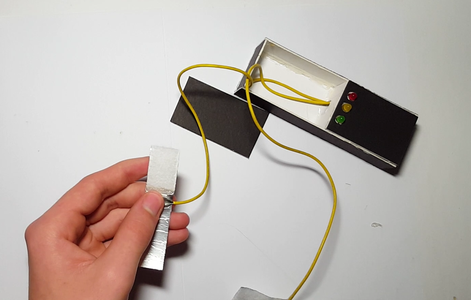
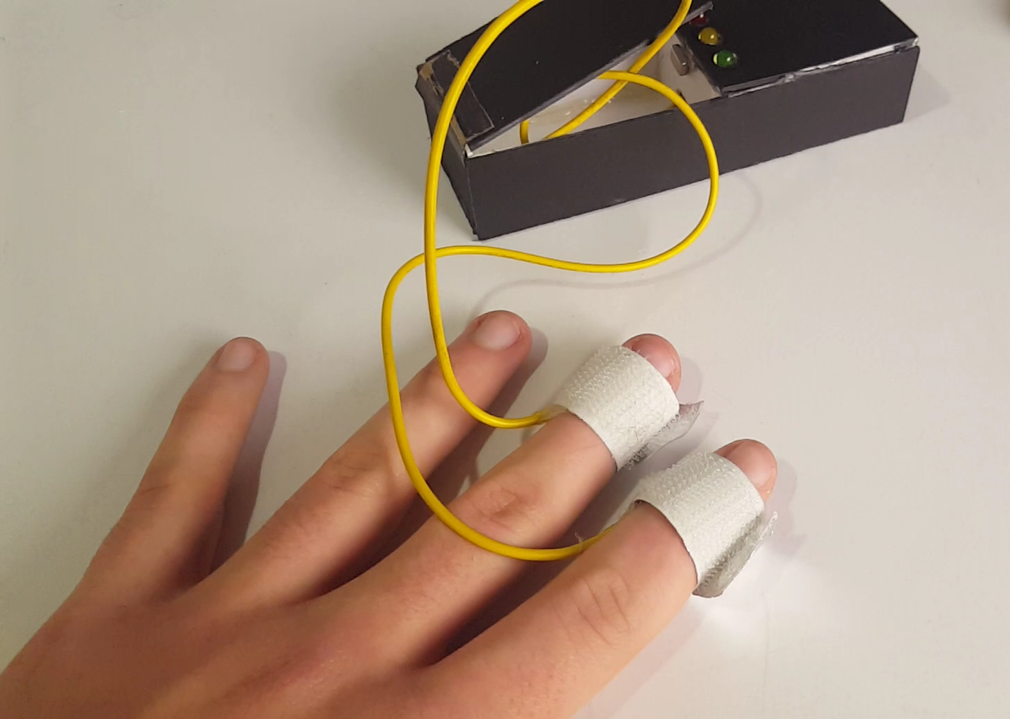
Now that the basic form of the project is done we can start adding features to make it easier to use we will start by adding finger clips to keep a stable connection between our fingers and the cables. Lets start by gluing a strip of tinfoil to the bottom of a strip of velcro, do this for both pieces of velcro (the hook and the loop. Now rap it around your finger until it makes a tight fit (check photos) then tape the exposed wire from analog pin 0 to the tin foil and repeat this step for the 5 volt pin (make sure it makes a good connection)
Step 6: Making the Case

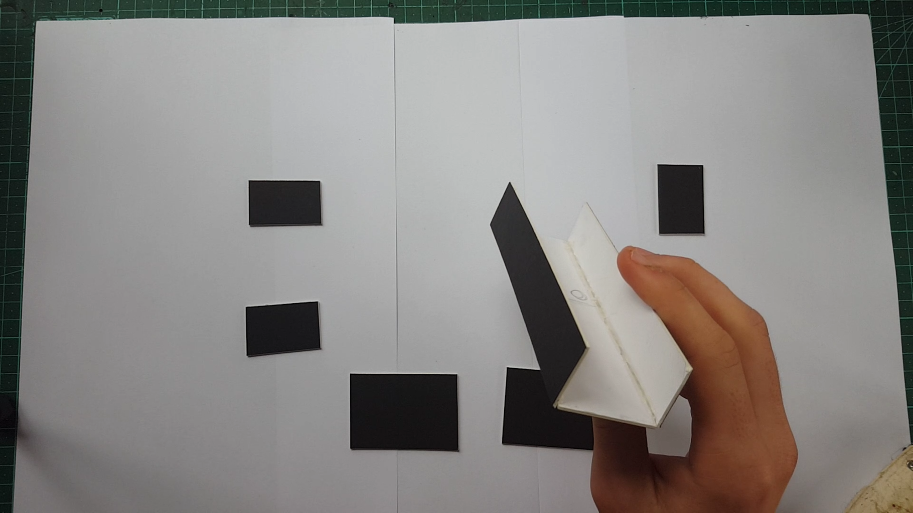
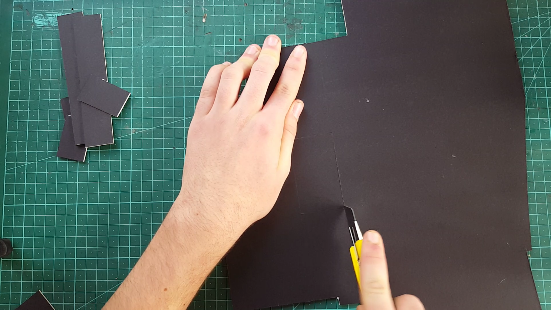
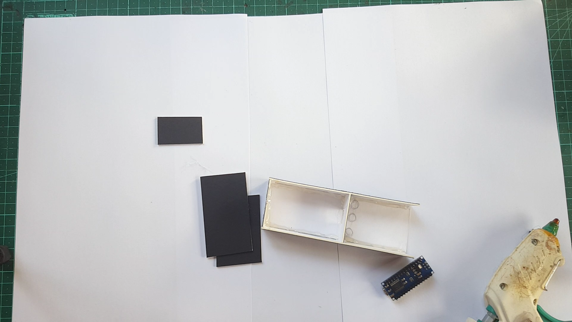
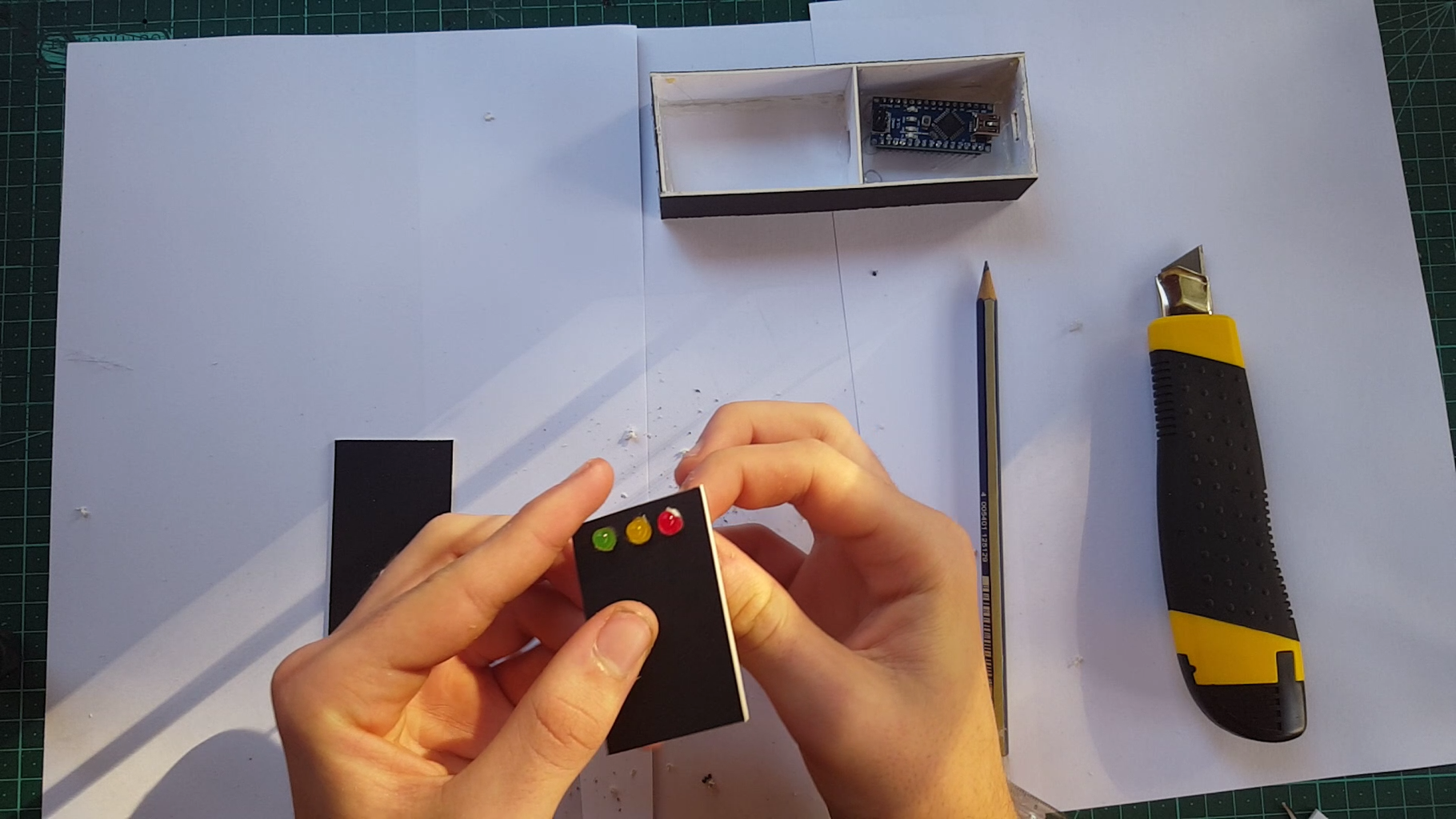
The plan is to make a small compartment for the finger pads to fold away and to have three holes for the leds to stick out. Its going to be made out of cardboard and to make it we will need to cut the following shapes out:
- Cut two 15x3 cm rectangles
- One 15x5 cm rectangle
- Three 5x3 cm rectangles (cut a square in the middle on one of them for the nanos usb)
- One 9x5 cm rectangle
- One 6x5 cm rectangle
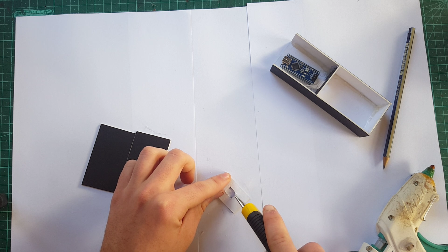
The 15x5 rectangle is the base. The two 15x3 rectangles and two of the 5x3 rectangles get glued to the sides of the base. Now glue the third 5x3 rectangle to the base 6cm from the side (close to the middle, check photos) Now you should have a rectangle thats divided into two sides, one with a length of 6cm and the other with a length of 9cm. The side with a length of 6cm is where we are going to put the electronics and the other side is where the finger pads go. Next cut 3 holes (the size of leds) on the 6x5 rectangle and glue it down to the 6cm side (as a lid). Last we need to tape the short side of the 9x5 rectangle to the far side of the 9cm side (this acts as a lid that flips up and down to reveal the finger pads)
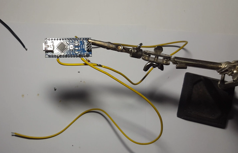
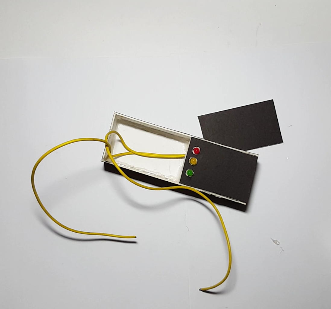
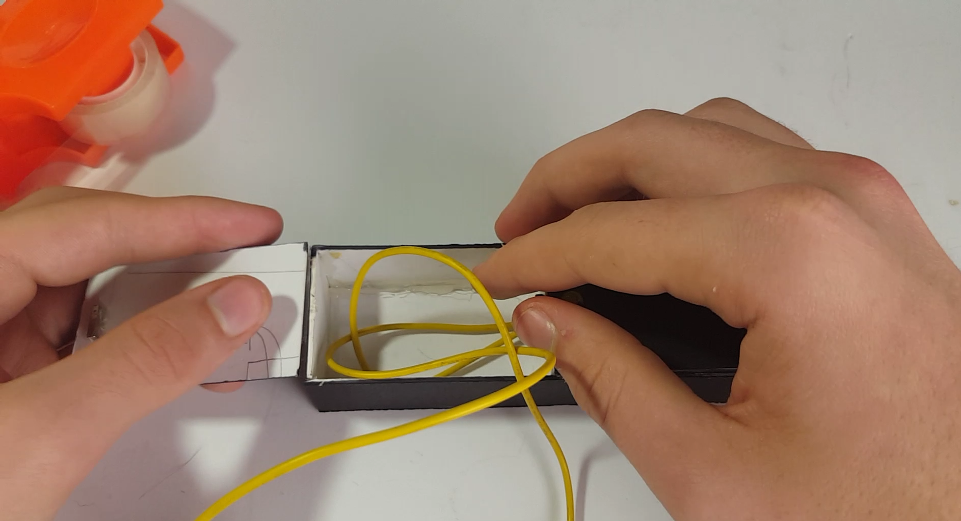
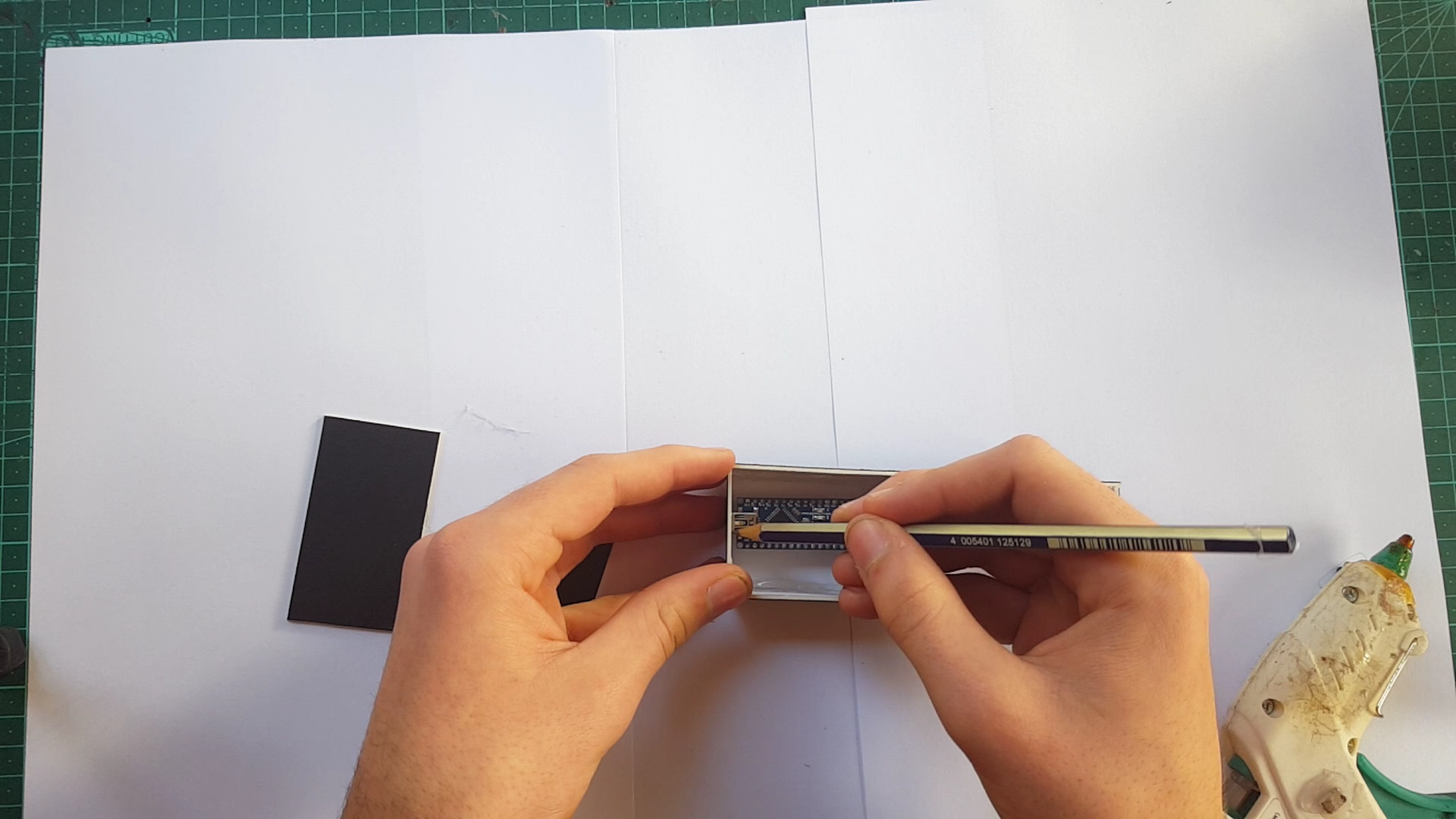
Step 7: Putting It All Together
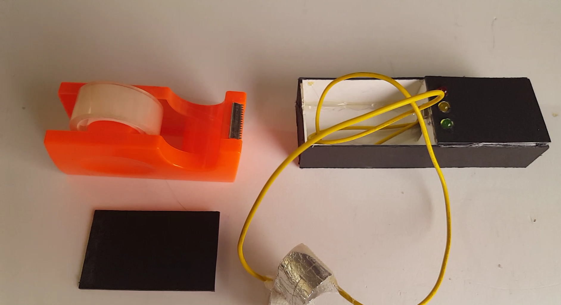
The last thing we need to do is put the electronics in the case start by gluing down the arduino and all wires in the 6cm side and run the extended wires(pin analog 0 and 5 volt) to the other side of of the rectangle (9cm side). Now glue the three leds to the holes we made on the 6x5cm rectangle and give it a test if all goes well you should have a small portable Arduino lie detector but let me warn you this isnt the most accurate system in fact most real lie detectors use a host of other sensors to determine if someone is lying such as a heart rate monitor and others, what im saying is dont uses the result of this for serious questions. :D
If you have any questions please either send me a personal message or leave a comment and ill try my best to get back to you.


