

Introduction: Arduino Line Following Robot for Beginners


* Updated 08/24/2013 to include more pricing, source information, and top/bottom/wheel templates
Mostly functional for general public, use at own risk!
Hey hey! This is a Programmable Line Following Robot for Beginners. This project is designed to work in tandem with our Arduino Traffic Light for Beginners instructable. However it will work just fine without!
We estimate this can take approximately 10 to 15 hours of work for someone who hasn't done any electronics or programming. If that's a bit much, we recommend checking out this instructable! Depending on how you source your parts, the average cost for this project will probably be between $40 and $60.
This project was designed for a summer camp at a Hackerspace in Ann Arbor, MI. If you aren't already familiar with what a Hackerspace/Makerspace is, we highly recommend you check one out! They can be a wonderful resource for both tools and information. Things like access to a LASER cutter can make this project look significantly better with minimal effort. Find one near you!
Suggested Tools
- Soldering Iron
- Wire Snips
- Pliers (Needle Nose Preferred)
- Wire Strippers (22 AWG)
- Utility Knife
- Phillips Head Screwdriver (No. 1)
- Pencil
- Arduino UNO
- Breadboard
- 9V Battery Holder with 2.1mm Barrel Connector
- LASER Cutter
- Heat Gun
Suggested Materials
- 1 x ($1.50) - Photocell (Sparkfun)
- 2 x ($2.26) - QRD1114 - IR Emitter/Sensor (Sparkfun)
- 3 x ($1.00) - 100 Ohm Resistors - Brown Black Brown (Sparkfun)
- 2 x ($1.00) - 220 Ohm Resistors - Red Red Brown (Sparkfun)
- 2 x ($1.00) - 270 Ohm Resistors -Red Purple Brown (Sparkfun)
- 2 x ($1.00) - 5.6k Ohm Resistors -Green Blue Red) (Sparkfun)
- 2 x ($1.00) - Yellow LEDs -Indicators Lights on Car) (Sparkfun)
- 2 x ($1.00) - Red LEDs -Brake Lights on Car (Sparkfun)
- 1 x ($17.00) - 22 AWG Solid Core Wire in Red, Black, Yellow, Blue, and White colors (Sparkfun)
- 1 x ($2.00) - Solarbotics Plastic Caster (Solarbotics)
- 2 x ($11.50) - DC Gear Motor (GM2) (Solarbotics)
- 2 x ($2.00) - NPN Transistors (Adafruit)
- 2 x ($1.50) - Diode 1N2001 (Adafruit)
- 1 x 9v Battery (Local Hardware Store)
- 1 x LASER Cut Acrylic Top Plate *
- 1 x LASER Cut Acrylic Bottom Plate *
- 2 x LASER Cut Acrylic Wheels *
- 2 x Thick Rubber Bands - 3.5cm diameter x 1cm width (Local Hardware/Craft Store)
- 1 x 8" Zip Tie (Local Hardware Store)
- 2 x ($0.50) - Machine Nuts - #3 1/2" Micro (Local Hardware Store)
- 2 x ($0.50) - Machine Screws - #3 1/2" Micro (Local Hardware Store)
- 2 x ($0.50) - Machine Screws - #2 1/4" (Local Hardware Store)
- 4 x ($0.50) - Machine Screws - (~1/8" Diameter, ~1.5" Length ) (Local Hardware Store)
- 12 x ($1.00) - ?? Nuts for Machine Screws(Local Hardware Store)
- 1 x ($2.00) - Double Sided Sticky Foam Tape ~10cm length x ~1cm wide) (Local Hardware Store)
- 1 x ($2.00) - White Electrical Tape Roll (Local Hardware Store)
- 1 x ($3.00) - Foam Core Board24x36" 1/4" thick
- 1 x ($3.00) - Heat Shrink Tube: 25cm of 3/32" (~2.4mm) diameter.
Highly Recommended
- Clean workspace
- Good lighting
- Someone awesome to work with
Short on resources?
- Find out if there's a local hackerspace near by!
- Need it today? Radioshack. Can you wait a few days? Adafruit, and Sparkfun are excellent resources.
Who made this?
- This instructable was brought to you by Khevna Shah and Josh Williams, and much help from the World's Friendliest Hackerspace: All Hands Active
* Don't have a LASER Cutter?
- See the PDF files! They contain a printable version of the Top and Bottom car plates, along with wheels. Print them out and purchase a sheet of 1/8" Baltic Birch. Along with a drill, a good assortment of bits and an appropriate saw will make for a classy wooden version!

Step 1: Prepare Your Workstation


Step 2: Solder IR Sensors


Step 3: Solder Photocell


Step 4: Solder Brake Lights


Step 5: Soldering Your Motors


Step 6: Mount Your Arduino & Breadboard!


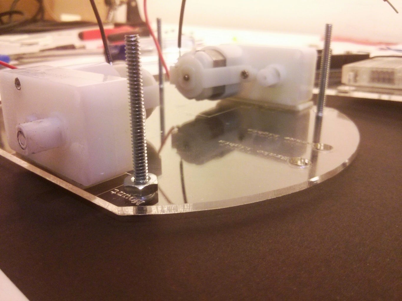
Step 7: Stack the Plates!


Step 8: Wheels & Casters!


Step 9: Insert Battery Pack & Brake Lights!


Step 10: Insert IR Sensors & Photocell


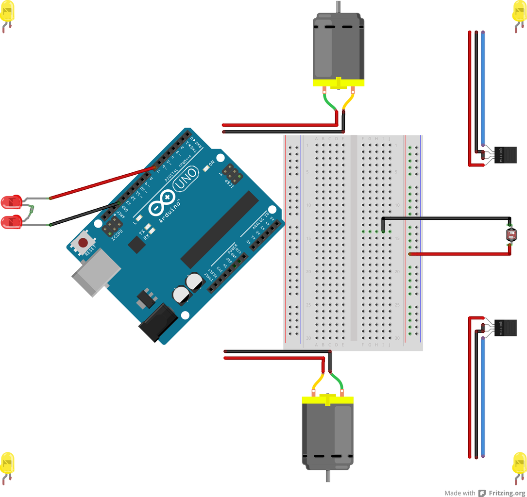
Step 11: Breadboarding!


Step 12: Code Review: Variables

For instance:
int GREEN = 2; has a type of int, a name of GREEN, and a value of 2.A variable gets created when you put the type in front of it! If you don't put the type in front, the variable is being used not created.
A variable is used in place of a value.
Anywhere you want to use a
2 you can use GREEN.A variable ONLY exists between the first { looking up and the corresponding (not nearest) } down in the code.
voidsetup()
   {
// a variable created in here doesn't exist in loop
   }

voidloop()
   {
// a variable created in here doesn't exist in setup
   }
Variable Types:
A number variable called an
int (short for integer). An int can be any whole number from -32,768 to 32,767. More details here: http://arduino.cc/en/Reference/IntA
long is like an integer but bigger! A long goes from -2,147,483,648 to 2,147,483,647. The word unsigned means that instead of going from -2,147,483,648 to 2,147,483,647, it goes from 0 to 4,294,967,295. Since time is never negative, we use an unsigned number for it!More details here: http://arduino.cc/en/Reference/Long
and here: http://arduino.cc/en/Reference/UnsignedLong
A
boolean can be either true or false just like an int has a range of -32,768 to 32,767.Step 13: Code Review: Functions

Let's talk about Instructions:
Functions are just like variables. Once you create them, you can replace the sets of instructions you put into the function in the rest of your program.
Turning this set of instructions:
void loop()
   {
  digitalWrite(GREEN, HIGH);
digitalWrite(YELLOW, LOW);
digitalWrite(RED, LOW);
}
Into this:
void loop()
   {
     green_light();
   }
void green_light()
{
digitalWrite(GREEN, HIGH);
digitalWrite(YELLOW, LOW);
digitalWrite(RED, LOW);
}
A function is used in place of instructions.
Anywhere you want to make a green light, you can now write
green_light();.Let's talk about outputs:
The setup and the loop function have outputs too. They're void. Void is computer language for nothing. Our function will output a boolean.
First you need to tell the Arduino that you want your function to output a
boolean.
Then you need to actually return (ouput) abooleanvalue.
An example of this is:boolean my_awesome_function()
{
boolean i_love_kittens = true;
return i_love_kittens;
}
Step 14: Code Review: If Statements

if statements like this: You can use the following comparisons:
if(sensor_value < sensor_mid)
   {
  // if sensor value is less than sensor mid do something
   }
else if  (sensor_value > sensor_mid)
   {
  // if sensor value is greater than sensor mid do something
   }
else if  (sensor_value == sensor_mid)
   {
  // if sensor value is equal to sensor mid do something
   }
// ... have as many else if statements as you want here
else
   {
  // do something else
   }
** Remember that ONE equal sign is used for setting information to variables and TWO is to compare!
<less than>greater than==equal to!=not equal to<=less than or equal to>=greater than or equal to&&and
Step 15: Code Review: While Loops

while loop is like an if statement, while the condition provided is true, it executes. The difference between an if statement and a while statement is that the while statement keeps on executing until the condition is false -- just like how the loopfunction runs until you turn off your Arduino.An example of this is:
while(current_time < end_time)
   {
  // do something

  // now update the current time
     current_time = millis();
   }
The code you put in the "do something" area will keep going until the time goes past end_time
Step 16: Code Review: LEDs

First, you need to tell the Arduino that you will
OUTPUT data on the pin you plugged the Green LED into.You can do this by using the
pinModefunction.
An example of this is:pinMode(3, OUTPUT);where my pin number is3.
Second, you need to send a
HIGH signal to the LED to turn it on! (A "LOW" signal will turn the LED off.)You can do this by using the
digitalWritefunction.
An example of this is:digitalWrite(3, HIGH);where my pin number is3.
Step 17: Code Review: Sensors

You can do this by using the
analogReadfunction.
An example of this is:analogRead(A0);where my analog pin number isA0.
The
analogRead function returns (outputs) an int (integer) between 0 and 1023.More details here: http://arduino.cc/en/Reference/AnalogRead
Here is an example piece of code that stores the value that is returned by the
analogReadfunction in a variable:
int SENSOR_PIN = A0;
int sensor_value = 0;

voidsetup()
   {
   }

voidloop()
   {
     sensor_value = analogRead(SENSOR_PIN);
   }
Step 18: Code Review: Calibrating

When calibrating, you want to start the low value at the maximum value (1023) and the high value at the lowest possible value (0).
Then you want to create a loop to run for about 5 seconds by creating a current time and end time variable.
In the loop, you want to read the sensor value.
If the sensor value is higher than the highest value, make the highest value the sensor value.
If the sensor value is lower than the lowest value, make the lowest value the sensor value.
Don't forget to update time!
At the end, set the mid value to be between the highest and lowest value ( (high+low)/2 ).
Step 19: Get Started!

Add in the basic program:
voidsetup()
   {
// code in here runs once
   }

voidloop()
   {
// after the setup function, code in here runs over and over
   }
Step 20: More Helpful Functions!
Next, you're going to create two functions!
A void move_car() function and a void go_straight() function!
Inside the move_car() function, let's tell the car to go_straight();.
Inside the loop function call your move_car() function.
In the next step, we'll learn how to make the car go straight!
** Don't remember functions? Look back at the code review for help!
Step 21: Making the Car Go Straight!
Next, just like the LEDs, we'll have to tell the Arduino that we'll be outputting to these pins by setting the pinMode.
int RIGHT_MOTOR = 11;
int LEFT_MOTOR = 3;
You can do this by using the
pinModefunction.
An example of this is:pinMode(RIGHT_MOTOR, OUTPUT);where my pin number isRIGHT_MOTOR.
Let's create an
int MOTOR_ON variable and set it to 105 because 105 is about as fast as our line follower can go and still make all the tight curves on our track.After that, instead of using
digitalWrite which only lets us write HIGH and LOW, we're going to use the analogWrite function. analogWrite allows you to write any number between 0 and 255 to the digital pins.You can do this by using the
analogWritefunction.
An example of this is:analogWrite(RIGHT_MOTOR, MOTOR_ON);where my motor speed isMOTOR_ON.
Now, in the
go_straight function, turn on both motors using the analogWrite function.
Step 22: What About Left and Right?
Create an
void go_left()

void go_right()
int MOTOR_OFF variable and set it to 0.To go right, the left motor needs to be on and the right motor needs to be off.
Remember to use the
analogWrite function.
Step 23: Functions With Inputs
We already talked about instructions and output, but we haven't talked about inputs. Inputs allow us to send information to functions.
Earlier in the project, we used the
pinModefunction. We sent the information about the pin number, 3, and mode, OUTPUT, to the function by passing in values. We called the function like this: pinMode(3, OUTPUT);Similarly, we can create our own custom functions with inputs. You can have as many inputs as you want!
Here is an example (we won't be using this!):
In our
voidloop()
   {
     feed_kitten(3);  // this calls feed_kitten with the number 3, this means that the
   //number_of_treats variable gets created with the value 3
     feed_kitten(10);  // now the number_of_treats variable gets created with the value 10
     feed_kitten(1);
   }

void feed_kitten(int number_of_treats)
   {
  // now every time feed_kitten gets created, it gets created with number_of_treats
   // defined as the number that was passed in.
   }
feed_kitten function, we're going to be telling that function a different number of treats.Function Syntax Example:
return_variable_type function_name(type variable_name, type variable_name, ... type variable_name)
   {
return_variable_type some_variable;
     some_instructions_here;
return some_variable;
   }
Step 24: IR Sensors: Reading Lows and Highs
SENSOR_PIN, SENSOR_MID, and SENSOR_INDICATOR, and returns true if the sensor is lower than mid and returns false otherwise.
boolean value_lower_than_mid(int SENSOR_PIN,int SENSOR_MID, int SENSOR_INDICATOR)
{
boolean lower_than_mid = false;

  digitalWrite(SENSOR_INDICATOR, LOW);

  int sensor_value = analogRead(SENSOR_PIN);

// if the sensor_value is less than sensor mid
// set lower_than_mid to true AND turn on your indicator (HIGH)
// your code here

return lower_than_mid;
}
Now can you create a function
value_higher_than_mid()?Create create a variable for the
boolean value_higher_than_mid(int SENSOR_PIN, int SENSOR_MID, int SENSOR_INDICATOR)
{
boolean higher_than_mid = false;

  digitalWrite(SENSOR_INDICATOR, LOW);

  int sensor_value = analogRead(SENSOR_PIN);

// if the sensor_value is greater than sensor mid
// set higher_than_mid to true AND turn on your indicator (HIGH)
// your code here

return higher_than_mid;
}
LEFT_SENSOR, RIGHT_SENSOR, and the MIDDLE_SENSOR. Set them to the corresponding pins on your Arduino board. (Look at your circuit). Can't figure out what to do with a sensor? Check the code review about sensors.Also create a variables for
left_sensor_mid, right_sensor_mid, middle_sensor_mid. Set these to 511 for now. We will calibrate them in the next step.Also, create a variables for
RIGHT_INDICATOR, LEFT_INDICATOR, MIDDLE_INDICATOR. These are your yellow front lights and your red brake lights.Remember to set your pin modes for all the lights to output in the
setupfunction.Note: For our stop light indicator, middle sensor, we're going to use
value_higher_than_mid. For the two IR sensors, left and right sensor, we're going to use value_lower_than_mid.Now try calling your new functions in your
loopfunction.Here is an example of how to call this function:
boolean saw_right = value_lower_than_mid(RIGHT_SENSOR, right_sensor_mid, RIGHT_INDICATOR);
boolean saw_left = ?
boolean saw_middle = ?
Try running your code! You'll see that every time the sensors see less than mid (or higher than mid) the lights will turn on.
Step 25: IR Sensors: Calibration Function 2.0
Try creating this function:
int calibrate(int SENSOR_PIN, int INDICATOR_PIN)
  {
int sensor_mid = 0;
int sensor_high = 0;
int sensor_low = 1023;

unsigned long current_time = millis();
unsigned long end_time = current_time + 5000;

// turn on your indicator light here (set it to HIGH!)
// your code here

while (current_time < end_time)
    {
    // now update the current time
      current_time = millis();

// get a new sensor_value here!
// your code here

// record the minimum sensor value
if (sensor_value < sensor_low)
      {
// your code here
      }

// record the maximum sensor value
// your code here
      {
        sensor_high = sensor_value;
      }
    }

// turn OFF your indicator light here (set it to LOW!)
// your code here

//set mid to be the MIDDLE! :)
    sensor_mid = (sensor_high + sensor_low)/2;

return sensor_mid;
}In the
setupfunction, try adding calibration for each sensor.Here is an example:
right_sensor_mid = calibrate(RIGHT_SENSOR, RIGHT_INDICATOR);
Step 26: Sensors + Car
First, we're going to modify our move_car function so that it takes in inputs!
Here is an example:
Next, in our
void move_car(boolean saw_right, boolean saw_left, boolean saw_middle)
loopfunction, we're going to call the modified move_carfunction.Now, let's make our
move_car function do more than go straight! We want to add the following if statements (review step 14) in move_car:If the front sensor sees something, then stop the car, do you have a stop car function yet? No? Add one!
If the right sensor sees something and the left sensor doesn't see something, turn right!
If the left sensor sees something and the right sensor doesn't see something, turn left!
If the right sensor and the left sensor both see nothing, go straight.
If the right sensor and the left sensor both see something, stop the car / go straight, YOU PICK!
Here are some example if statements to help you out:
if(saw_middle == true)
{
stop_car();
}
else if ((saw_right == true) && (saw_left == false))
{
// do something
}
else if((saw_right == false) && (saw_left == true))
{
// do something
}
// ... keep adding else if statements!
Step 27: The Final Code

This step will be up after camps are over!

Participated in the
Arduino Contest

Participated in the
Weekend Projects Contest


