

Introduction: Arduino Mario Clock


It's a musical desktop alarm clock with a theme of well-known MARIO game. Actually I like to wake up with the Mario theme instead of my cellphone. Also the LEDs (color tubes) blinking make it more beautiful.
Features:
- Display of Time, Date, Temperature
- Mario image and music on startup theme and alarm time
- Adjustable time, date, alarm
Used parts:
- 1x Arduino ProMini 5v
- 1x Nokia 5110 LCD
- 1x DS1307 module (real-time clock)
- 1x Speaker/Buzzer
- 1x DS18b20 Temp sensor
- 1x Electronic board
- 4x LED (different colors)
- 4x Push button
- 4x Resistor 220 (for LEDs)
- 5x Resistor 1K (4x for buttons, 1x for Temp sensor)
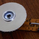
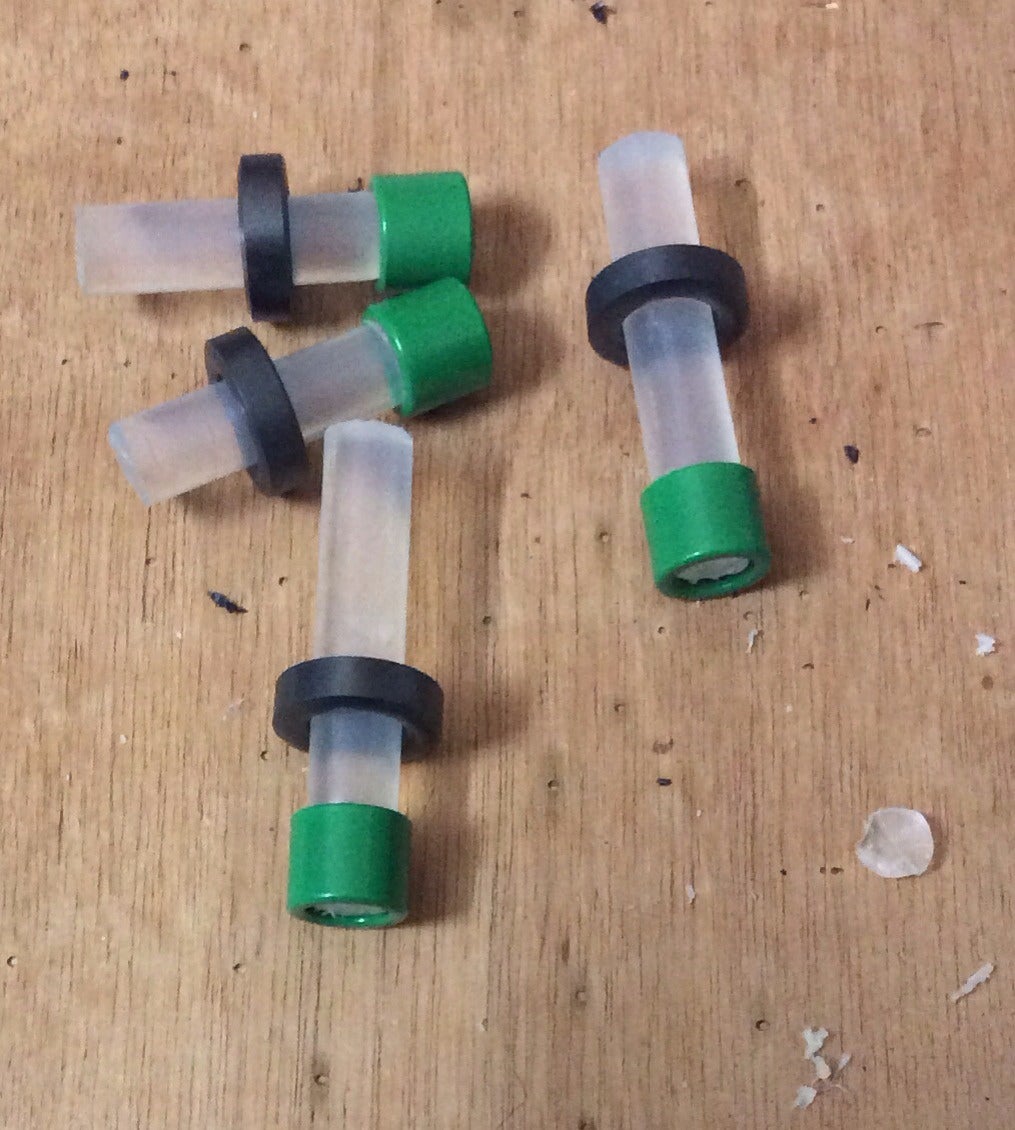
- 1x Hot glue stick (tube) which cut into 4 pieces 2x 6cm and 2x 8cm
- 8x metal rings and cylinders (I used Ferrite beads salvaged from my old printers)
- 1x Plastic box
- 5x mini battery, or 4x AA battery
- Tools: Hot-glue gun, soldering iron, pliers, some wires, ...
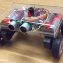
Step 1: Make a Desktop Clock Box


If you want to use it as a real desktop clock, so find a pretty box. I've used the soldering iron to melt the box and making holes for pushh buttons and the lcd.
Step 2: Make the Circuit


Attach the push buttons and resistors on the board. Fit the board in the box via hot-glue. Connect the LEDs under the glue tubes. Use the solderig iron to make a propper hole inside the tubes. Fit the parts like as temp sensor, rtc, batteries and others inside the box via hot-glue.
Step 3: Arduino Code

I've made a few images (Mario splash screen, Mario jump, Temperature icon, Alarm icon) with MSPaint which can be converted to binary data via LCDAssistant. All the coed is attached.
I think the code is enough plain and simple but, the following code hints can be helpful.
Classes:
- NokiaFa5110: Nokia LCD driver class.
- Util: Bitmap images.
- DS1307RTC, Time: Used for date time module.
- Wire, OneWire, DallasTemperature: Used for temperature sensor.
- EEPROM, avr/pgmspace: To use the EEPROM memory.
- Narcoleptic: A handy class to lower the battery usage via stand by delays.
Hints:
- A main switch-case and state variable used to handle the different menus and program states.
- The EEPROM memory has used to save the adjusted date and time variables.
- I've tried to partially refresh the LCD when the time, date or temp will change. The LCD is most battery consuming part.
- Narcoleptic class make it easy to lower the Arduino board battery usage, when there is no job to do (delay).


