

Introduction: Arduino Morse Code Shield


communication in the era of the telegraph. The code represents
alphanumeric characters by short and long intervals of signal -- those
familiar dots and dashes. For many years passing a Morse code test was a
prerequisite of getting a Ham license, but nowadays most radio amateurs
use it only infrequently. No longer are ship-to-ship distress signals
sent in Morse, as was the famous CQD (dah-dit-dah-dit dah-dah-dit-dah
dah-dit-dit) transmitted by the sinking Titanic's radio operator in 1912.
Still, Morse remains important for signalling distress, if only by a lost
hiker blinking a flashlight into the lonely, dark night.
Hacking the Arduino as a Morse code trainer is fairly straightforward.
All you need is a blinking light, such as a high-intensity LED, and a sound
source, say a mini piezo speaker, to provide the beeps. Rounding out
the project is an LCD display to show the character being beeped/blinked.
The goal is to beep and simultaneously display the letters, numbers,
and a few important punctuation marks in ordered sequence. Following
this, do 50 random letters. Then, have the entire routine repeat.
The combination of beeps, flashes, and LCD display serves as an
effective tool for memorizing the Morse code.
I built this project as an Arduino shield, using an Adafruit protoshield
blank board. It will likewise work with most of the commercially pre-built
16x2 LCD shields or even just breadboarded. The hardware consists of
an 8x2 or 16x2 LCD wired to the Arduino in conventional fashion, an LED,
and a piezo speaker. Most of the actual work is done by software.
I used point-to-point wiring, otherwise known as "haywiring," a
venerable technique lost in the mists of antiquity. Before the mid 1950s,
virtually all electronic devices were built this way, and by humans,
not robots or automatic devices.
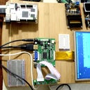
This is how the completed project works:
Step 1: What You'll Need to Build It


Materials:
blank protoshield board (Adafruit and Sparkfun sell nice ones)
8x2 LCD, type JHD802A-2 (the kind with no backlight preferred)
[This project will work just as well with a 16x2 LCD,
with one change on line 105 of the sketch.)
1 high-intensity LED
(Doesn't need to be the ultra-bright variety.
A "clear" LED works just fine.)
1 cheap piezo beeper
(All Electronics sells a plastic-encased one for $1.50,
which is nice and loud and non-polarized. Catalog # SBZ-26.)
1 220 ohm resistor
1 47 ohm resistor
Step 2: Pictorial Schematics


The illustration depicts the project built on a Sparkfun protoshield.
An Adafruit or equivalent board works just as well. Even a
general-purpose prototyping project board is fine, though it might
be a bit tricky to get the headers aligned just right.
You can even build the project on a wireless breadboard.
Note that the current-limiting resistor on the LED is 220 ohms, and the
one on the piezo speaker is 47 ohms. The LED needs that resistor, or it
will burn out. The speaker may or may not need one, but it's better to be
safe.
Step 3: Preparing the LCD Display


Let's pick up a soldering iron and begin!
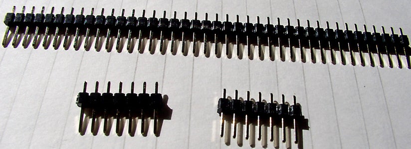
First, we'll solder two rows of 7-pin male headers to the JHD802A LCD display.
1) Snap off two 7-pin pieces of a row of male headers.
2) Push the 7-pin headers into a solderless breadboard, side by side,
long pins going into the breadboard.
This will hold them in proper alignment.
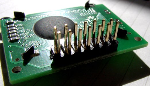
3) Line up the LCD connector holes with the headers and press the LCD
down flat. You may need a spacer of small block of wood to prop up the
other end of the LCD while you solder the pins on top. Carefully solder
each of the protruding short pins.
4) Now, onward to actually populating the protoshield.
Step 4: Installing the Headers


1) We'll begin by installing the male headers on the long sides of the
protoshield. The best way of aligning these headers is to plug
them (long pins down) into the female headers of an Arduino,
prior to positioning the protoshield on top and soldering.
Solder all 28 pins of the four headers.
2) In similar fashion, push the sets of female headers over the pins of
the male headers of a completed Arduino shield.
Then, position the protoshield upside-down atop the exposed solder pins,
similar to the previous step. Solder all 28 pins of the four headers.
3) We continue by populating the protoboard with the other components.
Step 5: Populating the Component Side


1) Insert and solder the two pushbuttons, the LEDs, and the
current-limiting resistors on the component side of the protoboard.
2) We can optionally add female header strips on the ground and +5v
distribution strips or buses. This might be useful for future mods.
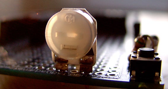
3) Position and mount a 10K mini trimpot, which provides the contrast
adjustment for the LCD. The far edge of the board is a good place
to stick it, so it doesn't get in the way of the other wiring.
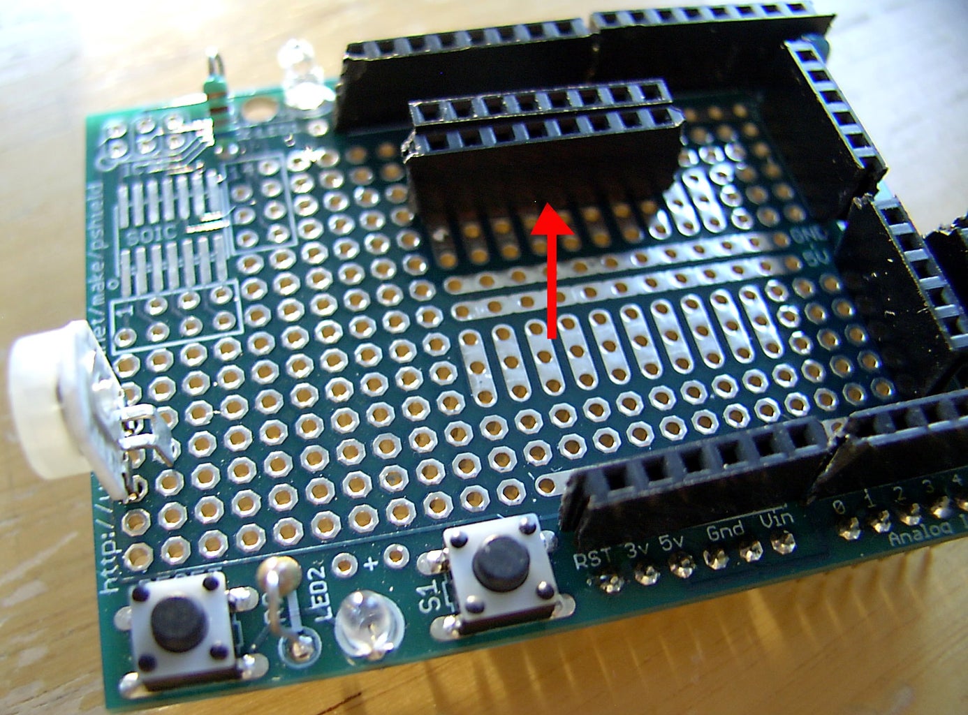
4) Now it's time to add two adjacent rows of 8-pin female headers for the
LCD. The easiest way to do this is to press the two rows of headers over
the pins previous soldered on the LCD. Then position both rows as a unit
in place, turn the board over, and solder them.
The 8-pin headers give the option of using an LCD display with backlight,
which has 16 pins. On a display without backlight, pins 15 and 16 are
not used.
If available, the tall "stackable" female headers are nice because
the pins give accessible soldering tie points on the underside of
the protoboard. After soldering, clip off the excess pin and wire ends.
Step 6: Connecting the LCD Socket


The LCD connects as follows.
LCD pin Pin name Connects to
-----------------------------------------------------------------------------
1 Vss Ground
2 Vdd +5 v.
3 Vee Center pin of 10k contrast pot
4 RS (reg. select) Arduino digital 8
5 RW (read/write) Ground
6 E (enable) Arduino digital 6
7 DB0 N.C. (not connected)
8 DB1 N.C.
9 DB2 N.C.
10 DB3 N.C.
11 DB4 Arduino digital 4
12 DB5 Arduino digital 5
13 DB6 Arduino digital 6
14 DB7 Arduino digital 7
15 A (BL+) +5v. (not connected if no backlight)
16 K (BL-) Ground (not connected if no backlight)
Notes:
1) This is identical to the wiring on most commercially-made
Arduino LCD shields. You may hook up pins 4, 6, 11-14 to different
Arduino digital pins if you change line 31 in the sketch.
2) A JHD802A-2 8x2 no-backlight LCD has only 14 pins, so ignore
pins 15-16, above.
We will now wire up the two rows of 8-pin headers to conform with
the above.
Pinout of JHD802A 8x2 LCD
Top View
2 4 6 8 10 12 14
o o o o o o o
o o o o o o o
1 3 5 7 9 11 13
Bottom View
14 12 10 8 6 4 2
o o o o o o o
o o o o o o o
13 11 9 7 5 3 1
As necessary, run wires on the bottom of the protoboard to make
connections.
Here, we see the advantage of using stackable headers with long pins.
After soldering, the pins are clipped.
Still more connections remaining on the bottom of the board. Be patient,
take your time, and double-check your work.
Step 7: Finishing the Wiring


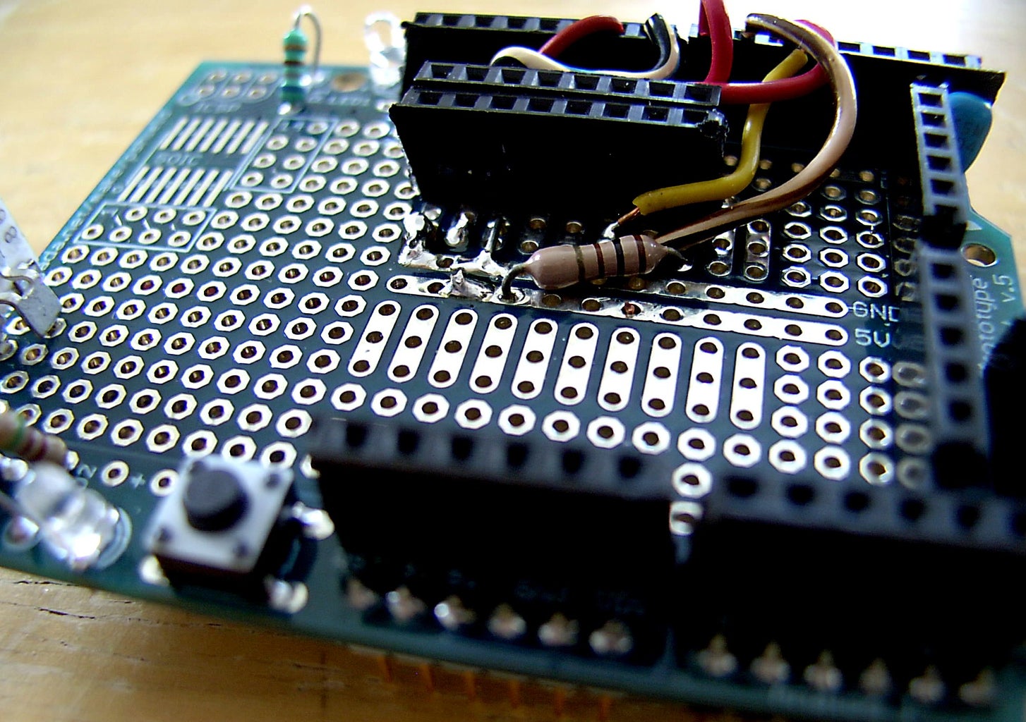
We will now complete the wiring on the component side of the board.
For maximum flexibility, the LCD control and data connections are wires
soldered to the appropriate terminals on the LCD (2x8 header) socket,
and then routed to and pushed into the female headers for the Arduino's
digital pins on the protoboard.
Position and solder the LED and the piezo speaker. The positive lead
for each of these is a wire that will be inserted into the appropriate Arduino
digital (female) header pin -- digital 10 for the speaker and digital 12 for
the LED. This is defined in lines 39 - 40 of the sketch.
Wire up the trimpot -- one end-terminal to ground, the other end-terminal
to +5v (it doesn't matter which one). The center terminal goes to pin 3 on
the LCD.
Double check that you have installed the current-limiting resistors for the
LCD backlight (if applicable) and for the piezo speaker. You should have
done this in Step 5.
All done? Recheck the wiring against the directions and pictorials.
Use an ohmmeter to test for shorts between the +5v and ground busses.
Finally, plug the board into an Arduino and see if it appears to power
up normally. All okay? Try it again with the LCD plugged into its socket.
Adjust the trimpot until you get a display.
Time to fetch the code.
Step 8: Final Steps


Download the sketch here:
http://bash.deta.in/morse8x2.ino
or here:
http://www.mediafire.com/file/bokbku7bsbtfd7b/morse8x2.ino
Now, program it into the 'duino, and cross your fingers.
Power it up, and if you're getting beeps and boops and flashes,
and an appropriate display on the LCD, then you can pat yourself
on the back and start to learn Morse code.
---
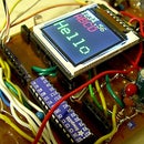
The last pic shows how it looks if you use an 8x2 backlit display.
Easier to see in dim light, but it has a bigger, clunkier footprint.
And, by the way, this DIY shield is shown here mounted on a DIY "hackduino"
build on a Radio Shack 276-168 project board. Perhaps that will be a
topic for a new Instructable at some future time.

Participated in the
Arduino Challenge


