

Introduction: Arduino Nano: BMP180 Barometric Pressure and Temperature I2C 2 X 16 LCD Display With Visuino


The BMP180 is a very popular combined Temperature and Barometric Pressure Arduino sensor. I already made Instuctable with BMP180. A number of people however asked how you can connect another I2C device on the same I2C bus as the BMP180. Finally I have found a chance to make such Instructable.
In this Instructable, I will show you how easy it is to connect 2 I2C devices on the same I2C bus - in this case a BMP180 and I2C LCD Display, and program the Arduino with Visuino to show the Pressure and Temperature on the Display.
Step 1: Components

- One Arduino compatible board (I use Arduino Nano, because I have one, but any other will be just fine)
- One BMP180 Sensor Module
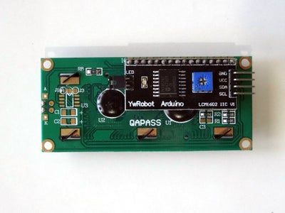
- One I2C 16x2 LCD Display (Back side of the LCD with the I2C adapter showed on Picture 2)
- One small Breadboard (Any breadboard can be used, or any other way to connect 3 wires together)
- 9 Female-Male jumper wires
- 2 Female-Female (Black) jumper wires
Step 2: Connect the LCD Module to the Arduino

- Connect Female-FemaleGround(Black wire) to the LCD Module (Picture 1)
- Connect the Female end of Female-MalePower(Red wire), SDA(Green wire), and SCL(Yellow wire) to the LCD Module (Picture 1), and leave the Male ends unconnected
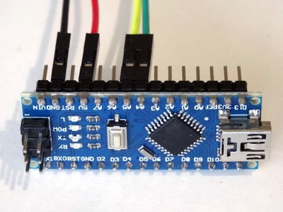
- Connect the other end of the Ground wire(Black wire) to Ground pin of the Arduino board(Picture 2)
- Connect the Female end of another Female-Malewire(Green wire) to SDA/Analog pin 4 of the Arduino Nano board(Picture 2), and leave the Male end unconnected
- Connect the Female end of another Female-Malewire(Yellow wire) to SCL/Analog pin 5 of the Arduino Nano board(Picture 2), and leave the Male end unconnected
- Connect the Female end of another Female-Male Power wire(Red wire) to the 5V Power pin of the Arduino board(Picture 2), and leave the Male end unconnected
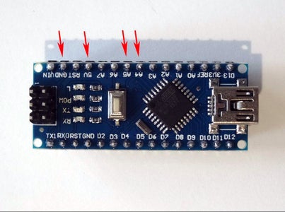
- Picture 3 shows where are the Ground, 5V Power, SDA/Analog pin 4, and SCL/Analog pin 5 pins of the Arduino Nano
Step 3: Connect the BMP180 Module to the Arduino


- Connect Female-FemaleGround(Black wire) to the BMP180 Module (Picture 1)
- Connect the Female end of Female-MalePower(Red wire), SDA(Green wire), and SCL(Yellow wire) to the BMP180 Module (Picture 1), and leave the Male ends unconnected
- Connect the other end of the Ground wire(Black wire) to Ground pin of the Arduino board(Picture 2)
- Picture 3 shows in Red where is the Ground pin of the Arduino Nano (In Blue are shown the pins connected in the previous step)
Step 4: Connect the Power, and I2C Wires Together


- Connect the Male ends of the 3 Power wires(Red wires) - from the Display, the BMP180 Module, and the Arduino together as example with the help of a Breadboard (Picture 1) - In my case I used a small Breadboard
- Connect the Male ends of the 3 SDA wires(Green wires) - from the Display, the BMP180 Module, and the Arduino together as example with the help of a Breadboard (Picture 2) - In my case I used a small Breadboard
- Connect the Male ends of the 3 SCL wires(Yellow wires) - from the Display, the BMP180 Module, and the Arduino together as example with the help of a Breadboard (Picture 2) - In my case I used a small Breadboard
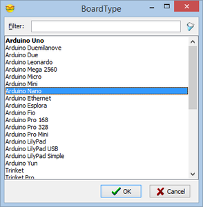
Step 5: Start Visuino, and Select the Arduino Board Type
To start programming the Arduino, you will need to have the Arduino IDE installed from here: http://www.arduino.cc/.
Please be aware that there are some critical bugs in Arduino IDE 1.6.6.
Make sure that you install 1.6.7 or higher, otherwise this Instructable will not work!
The Visuino: https://www.visuino.com also needs to be installed.
Step 6: In Visuino: Add and Connect LCD Component


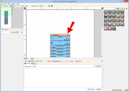
- Type "lcd" in the Filter box of the Component Toolbox then select the "Liquid Crystal Display (LCD) - I2C" component (Picture 1), and drop it in the design area
- Connect the "Out" pin of the LCD component to the to the "In" pin of the "I2C channel" of the Arduino component (Picture 2)
Step 7: In Visuino: Add, and Setup Text and Analog Value Elements to Display the Pressure


We will add a Text field with the description of the value, and Analog field to display the value for the Pressure and Temperature values.
First we will add Description and value fields for the Pressure:
- Click on the "Tools" button to open the Elements editor (Picture 1)
- In the "Elements" dialog select the "Text Field" in the right window, then click on the "+" button on the left to add Text Field (Picture 2)
- In the Object Inspector set the "Initial Value" property of the element to "Pressure:" (Picture 3) - This will specify the text to be displayed
- In the "Elements" dialog, select the "Analog Field" in the right window, end then click on the "+" button on the left to add Analog Field (Picture 4)
- In the Object Inspector set the "Column" property of the element to 9 (Picture 5) - This will specify the starting column of the field
Step 8: In Visuino: Add, and Setup Text and Analog Value Elements to Display the Temperature


Next we will add Text and Analog elements for the Temperature:
- In the "Elements" dialog select the "Text Field" in the right window, then click on the "+" button on the left to add Text Field (Picture 1)
- In the Object Inspector set the "Initial Value" property of the element to "Temp:" (Picture 2)
- In the Object Inspector set the "Row" property of the element to "1"(Picture 3) - This will specify the field to be displayed in the second Row
- In the "Elements" dialog, select the "Analog Field" in the right window, end then click on the "+" button on the left to add Analog Field (Picture 4)
- In the Object Inspector set the "Column" property of the element to "9"(Picture 5)
- In the Object Inspector set the "Row" property of the element to "1"(Picture 6)
- Close the "Elements" dialog
Step 9: In Visuino: Add and Connect BMP180 Component


- Type "bmp" in the Filter box of the Component Toolbox then select the "Pressure BMP180" component (Picture 1), and drop it in the design area
- Connect the "Out" pin of the Pressure1 component to the to the "In" pin of the I2C channel of the Arduino component (Picture 2)
- Connect the "Pressure" output pin of the Pressure1 component to the "In" pin of the AnalogElement1 of the LiquidCrystalDisplay1 component (Picture 3)
- Connect the "Temperature" output pin of the Pressure1 component to the "In" pin of the AnalogElement2 of the LiquidCrystalDisplay1 component (Picture 4)
Step 10: In Visuino: Add and Connect Clock Generator Component


We can use the project as it is, however it will refresh the LCD very fast all the time. It is better if the LCD is updated as example once a second. For this we will add a clock component to clock the reading from the sensor and the updating of the LCD.
- Type "clock" in the Filter box of the Component Toolbox then select the "Clock Generator" component (Picture 1), and drop it in the design area
- Connect the "Out" pin of the ClockGenerator1 component to the "Clock" input pin of the Pressure1 component (Picture 2)
Step 11: Generate, Compile, and Upload the Arduino Code


- In Visuino, Press F9 or click on the button shown on Picture 1 to generate the Arduino code, and open the Arduino IDE
- In the Arduino IDE, click on the Upload button, to compile and upload the code (Picture 2)
Step 12: And Play...


Congratulations! You have completed the project.
Picture 1 shows the connected and powered up project. As you can see on the picture, and in the Video the Display will show the pressure and the temperature.
On Picture 2 you can see the complete Visuino diagram.
Also attached is the Visuino project, that I created for this Instructable. You can download and open it in Visuino: https://www.visuino.com
Attachments


Participated in the
Sensors Contest 2016


