

Introduction: Arduino Pitch Detection Algorithm (using AMDF)


Last Update: January 16, 2016 (Recently added an improved matlab code (step7) with samples and lots of notes)
Foreword: This Instructable is written in a style to show how I analyzed, tested, implemented, and optimized an algorithm. Also, In the process, I learned how much work goes into doing each step and I've garnered more respect for those who have built other algorithms for my naive mindset.
Additionally, any critiques are very welcome!
Motivation: I needed to retrieve frequency data from a violin pickup. The work I did with another project creating a color organ had an FHT and I thought it would be easy enough to adapt it to my use. Trying to use it proved difficult since a violin creates what is called "quasi-harmonic" tones. Basically, the periodic frequency of the waveform was never the dominant one and I could only pick up higher harmonics of a single tone. Frustrating! So I had to build my own PDA because of the lack of search results for Arduino based PDA's. I ended up implementing the AMDF (autocorrelation magnitude difference algorithm).
Thanks: To Amanda Ghassaei for providing a general framework for how to build and test your own algorithm. I tried using her work on another Instructable:
But the core of the work she did didn't help me as much as it I wanted it to. So from there I looked for pitch detection algorithms and it got me too do all of this work. She has some pretty neat projects! Check out her website which is linked in the Instructable above.
Step 1: The Algorithm
Credit:
I am not sure who invented the algorithm but from what google tells me a British statistician by the name of George Udny Yule had published a paper in the late 1800's in reference to partial autocorrelation algorithm. Additionally there a bunch of papers published by the IEEE starting in the early 1900's citing improvements to the method for use in electronics.
AMDF - Here's the skinny:
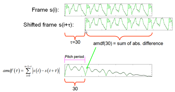
AMDF (N) = 1/N * Sum (i = 0 -> N) of ( | x(i) - x(i+N) | )
AMDF (autocorrelation magnitude difference function) is basically tracing overlapping lines on a given window of samples. Here is what basically happens:
1.) Gather data to form a window of N*2 samples wide.
2.) Cut the window in half.
3.) Overlay the first half over the top of the second half.
4.) Take the absolute value of the difference in the area between the two waveforms and sum it up.
5.) Divide the sum by the number of samples.
6.) Repeat steps 2 through 6 for a full sweep of all delays N that you expect to occur or be present in a waveform.
7.) If a quasi-harmonic tone is present, the AMDF will output a low number at or close to 0 at some delay N.
8.) Divide the sample frequency by your delay N, and you've got the most probable frequency of the quasi-harmonic tone.
A big note however! The AMDF does not work on more than one tone at a time. You won't be able to differentiate between double stops, multiple strummed notes, etc.
Other Algorithms:
As far as my research has taken me, there are a couple of other pitch detection algorithms out there. Obviously more, but I didn't search too extensively. I won't cover them but I will mention them hear for your further research if you so choose.
Of course, the original autocorrelation method is out there which is the basis of AMDF. The advantage of AMDF over basic autocorrelation is that the AMDF has a bunch of subtractions and additions with one division (which can be coded into a multiplication). For the Arduino Uno which is native 8bit architecture and doesn't have hardware division or multiplication, this is an absolute plus.
Another pitch detection algorithm is the Yin algorithm. This algorithm boasts a very low percentage error rate with each step of the algorithm detailing its effectiveness so that you can implement as much or as little as you'd like. From testimonials I've read it is not very computationally intensive which is great! So yeah... Why I didn't got there is because the Yin algorithm apparently has a patent on its use. Additionally, if you search around, someone has already compiled the source code for you in C so that you can play around with it. There is a published paper on the Yin algorithm as well, very interesting stuff.
Here is the Yin Source Code, if you want to take a look!: http://mroy.chez-alice.fr/yin/index.html
Here is the published paper on the algorithm: http://recherche.ircam.fr/equipes/pcm/cheveign/pss/2002_JASA_YIN.pdf
Step 2: Restrictions of the Platform


The Arduino Uno (ATMega328P or non "P") and its inherent Limitation
Arduino's are fun, but they are natively simple as far as computational power. Your computer is most likely a 64 bit machine, meaning that you can perform arithmetic on binary numbers 64 bits long. The Uno has only 8 bits which is one eighth the bandwidth plus a major frequency gap (~2Ghz to 16mhz) and not to mention cores and blah blah blah...
Meaning, that using an Uno is computationally at a disadvantage. Simple port manipulation for led`s and small motors are good enough for that purpose, but algorithms that want to crunch a bunch of numbers while maintaining proper time is quite difficult to get sufficient speed and accuracy.
A lot of the below consideration are limits that are specific to the Arduino Uno and I am analyzing them as an exercise in engineering principles. As a future engineer (I'm still in college, yahoo), I had to analyze all aspects of the problem. For my purposes, I had already understood that 8 bits isn't sufficient so I bought an Arduino Due so I can stay within the native 32 bit precision of an integer datatype (in the mail on the way). Using a mathematical tool such as Matlab, I was able to make that determination before I even coded on the Arduino Uno. You can see images of the tests I did on some waveforms in the next step. But, I continued on with the 8 bit approach just for ***** and giggles.
8 Bit Limit
Counting from 0 to 255 kind of sucks. Especially when you are doing a mathematical operator that needs to remain within that limit. So your actual precision for that kind of operation actually drops from 8 bits to 7 bits in order to add and stay within that window of binary numbers.
If it is not apparent to you, the reason is overflow. Overflow occurs in a electronic device when you try to do a mathematical operation which goes out of bounds of the limits. So, for example, subtracting -128 from 128 gives you (128 + 128) = 256. Boom... mathematical algorithm broken.
Coded Datatypes above 8 Bits
Adding two 8 bit numbers takes one instruction cycle natively, while adding a 16 bit integer will taken no less than three instruction cycles. This may not sound like a lot since one cycle is the inverse of the crystal frequency (16Mhz ^ -1) which is about 63ns. Here in lies the problem with multiplying the instruction cycles by 3; At the very minimum, when you need to do 400 subtractions, 400 additions (into a larger datatype so 800 instruction cycles), then a division (which takes 200+ instruction cycles) which is just one iteration of approximately 200 more iterations... your relatively slow clock speed becomes very apparent to you.
ADC 10 bit Precision
The ADC on an Uno has 10 bit precision, but based upon the previous restriction of 7 or 8 bits, you know you can't use it all; It will just be a waste of computational power to use the full width. Also, using analogRead() is just a wasteful expense of time. Look into direct port manipulation!
Step 3: Simulations


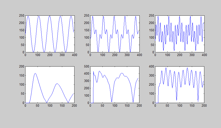
The pictures above just show some of the analyzing I did in Mat lab. Sorry for not labeling fully. But you can see that I did some simulations of the algorithm before implementing the algorithm. This at least showed me what the algorithm would do and what expected returns I could get.
First Image:
Just did a simple sine wave. Notice the dip at the second harmonic! I didn't code a harmonic detector in the code yet, but it is needed!
Second Image:
Did a test run with a quasi-harmonic tone. I used a method known as clipping to try to get the algorithm to give clear distinctions in calculations. Clipping is a form of "feature detection" and is commonly used in autocorrelation algorithms and is useful because quasi-harmonic tones will have such a feature unless it doesn't and the amplitude modulates constantly. But in this case, the violin doesn't modulate that much from frame to frame. It has not yet been implemented in the code. Trying to find a effecient way of implementing peak detection and relative gap difference for deleting samples below such a limit.
Third Image:
Tried to see how poorly the algorithm broke down when clipping was a constant rather than a percentage of a calculated peak.
Fourth Image:
Re ran the first and second images without clipping on 8 bit precision numbers from the ADC and 16 bit additions of the sums. I did 7 bit precision numbers as well but didn't take a picture.
Step 4: The Circuit

I stole this picture from Google images since this is outside of the scope of this tutorial. But is provided as a reference
But the gist of the input circuit is:
1.) Analyze the range of your source
2.) Offset by 2.5v so you can see positive and negative peaks
3.) Build an amplifier so that the maximum peak to peak amplitude of your signal is within the 5v to 0v window.
Note: Ensure the amplifier configuration doesn't add too much noise, ensure the amplifier is fast enough!, doesn't add too much phase shifting, and doesn't draw too much current from source, etc.
Step 5: Code, Output and Speed
Once I build my controller where the code is intended to be implemented I will post more pictures, but here is the code. It is pretty well documented and commented so I sparred all the commenting on this page.
The code ran on a atmeag328P takes 52ms to complete each cycle which analyzes for frequencies 196hz to 3136hz (frequency range of a violin). Notice that adjusting the range of delays to test for will greatly affect your speed!
Update July 21, 2015: Based upon my needs, I didn't really care if the higher frequencies above 3000hz got aliased since my needs were based upon the violin fundamentals ranged from 196hz to 3136hz. Thus, decreasing the ADC sample frequency to 19.2khz which allows the processor more time to process the available data. The use of a 64 scalar resulted in a 17ms execution time, but reduced the 3136hz to only 12 samples for amdf. Going slower would probably improve speed further, but higher frequency resolution is lost. The code does not reflect this change.
You can adapt it to use integers for higher precision if you want.
You will need to probably substitute the code for the display for a serial command or something like that.
Attachments

Step 6: Code Revision 2
This iteration tries to squeeze every inch out of the platform with the same hardware.
To summarize the changes.
1.) Pushed prescalar to 64, so sampling is at 19.2khz
2.) Slower samples, fewer iterations, faster processing of window
3.) Harmonic Detection and compensation
4.) Achieves a better and faster frequency estimation in 16ms versus the previous 52ms.
5.) The window is limited further with good precision only in 196hz to 1282hz range.
6.) estimations outside of this frequency range causes erratic behavior and/or aliasing.
7.) For my purpose, this limits the violin pitch detection to approximately harmonic E... but who needs to go into the stratosphere? haha.
Attachments
Step 7: Code Revision 3 - Using Matlab


So there were much improvements to the algorithm over the past couple of months after I took signal processing class and what not. So...
The "matlab_hps_testing" file contains scripts to run in matlab, along with audio file sources. The audio sources come from a specific open source lab which were free to use. I cannot remember the name and I am currently trying to find the website again, so please forgive me for not giving appropriate credit just yet!
Overall, the AMDF algorithm is used in conjunction with a HPS (harmonic product spectrum) to allow for the lowest AMDF harmonic to override the other harmonics. It is heavily annotated so I won't put all the remarks here.
Attachments
Step 8: Conclusions

The greatest limiting factor of this code is the low frequency analysis. It needs to do all the calculations on 392 samples for low frequency analysis at 196hz. A particular source of further improvement would be calculating on every fourth sample at lower frequencies.
Instead of calculating on 392 samples just pick intervals within that range so doing math on half or quarter the number of samples could be beneficial. However, the problem then becomes anti-aliasing, or the false impression of a signal due to harmonic multiples showing up in the data. Which could be offset by random interval points? If you dont know what anti-aliasing is here's a quick example. Remember watching car wheels rotate? Based on the light which allows you to see it, a wheel actually moving forward may appear as if its rotating backward. The light source (60hz incandescent bulb) just like the sampling rate, and your eye just like the algorithm, will process that information in a particular way to give you a false impression.
I haven't fully analyzed if its worth the effort yet. I will report back and update when I do!


