

Introduction: Arduino Projects on a Breadboard (no Serial Com)


Intro:
If you've got an Arduino Uno and want to start duplicating projects without having to buy an Uno every time... get ready to live! This instructable will show you how to move your projects (that do not require serial communication) onto a breadboard for prototyping or expansion. If you're looking for a more permanent solution check out these (breadboard ) (options ).
Stuff You Should Have Already:
-Arduino Uno & USB cord: You're gonna need this to program the new ATmega328
-Wire Strippers & Leatherman: A must have for wire management
-Solder & Soldering Iron: Great for sticking stuff to other stuff
-22 AWG Wire: Makes this project really difficult if you don't have it
Stuff To Buy:
Breadboard ...................................1x $ 8.00
LM7805 ..........................................1x $ 0.50
16 Mhz Crystal .............................. 1x $ 0.40
Push Button ...................................1x $ 0.11
220 Ohm Res ............................... 2x $ 0.10
10K Ohm Res .............................. 1x $ 0.05
22 pF Cap ...................................... 2x $ 0.12
10 uF Cap ...................................... 2x $ 0.10
Green LED ......................................1x $ 0.10
Red LED ......................................... 1x $ 0.09
ATmega328 (with Bootloader) ....1x $ 5.50
9V DC power Supply .....................1x $6.95 (get these for like $1 at thrift stores)
TOTAL ............................................... $22.02
Step 1: The Power Supply


Step/Pic 1: Wire up the bottom of your board so that you will have power on both side rails
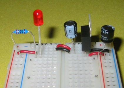
Step/Pic 2: Pop these little pieces of wire in, the tags will show you whats coming next
Step/Pic 3: Install your hardware, here are some things to note: the cathode (long leg) of the LED gets plugged into power. Unlike resistors, aluminum electrolytic capacitors have a positive and a negative lead. The leg with the gray strip above it means it is GND, and the longer leg is positive.
-A 10 uF capacitor needs to be tied to PWR and GND before and after the voltage regulator. Make sure the long wire goes to power, and the gray lead goes to GND.
-The LM7805 will straddle the 3 power lines; 9V DC in at the top (pin 1), GND at the middle (pin 2), and 5V DC out at the bottom (pin 3).
-Make sure your resistor is in series with the LED, it keeps the current through the LED from getting too high.
Step/Pic 4: Cut off the plug on the power supply, and solder on a little colored 22 AWG on the ends. The wire with the white strip on it will be PWR, the other is GND.
DANGER! make sure these two leads never touch while the power supply is in your wall. It will probably explode and catch fire, and will definitely burn up your power supply.
Step 5: Once you're sure everything is hooked up correctly, plug in your power supply and your little LED should light up (this is what we want)
Step 2: Upload Some Code


Step 1: Make sure the ATmega328 you buy has an Arduino bootloader burned on it already. Swap the ATmega328 out of your Uno with the fresh one you just got in the mail. Double check to make sure the IC isn't upside down.
Step 2 (Pic 1): Crack open the Arduino software and load a simple program. I chose Blink, a small program that will cause an LED on pin 13 to blink on and off.
Step 3 (Pic 2): If you bought the ATmega328 in this instructable, then you've got one with the Duemilanove bootloader on it. Make sure your software knows it too.
Step 4 (Pic 3): Plug your Uno board into the computer and upload Blink to the IC!
Step 3: The ATmega328


Step/Pic 1: Plug in the ATmega328 and your push button. With your 22 gauge wire, make the following VCC & GND connections to the IC:
-Pin 2 (RX) : GND
-Pin 3 (TX) : GND
-Pin 7 (VCC) : VCC
-Pin 8 (GND): GND
-Pin 20 (AVcc) : VCC
-Pin 21 (AREF): VCC
-Pin 22 (GND) : GND
The image tags will give you a clue as to what goes where for the next step.
Step/Pic 2: Hardware time! Things to note: ceramic disc capacitors (like resistors) have no positive or negative lead. In this instructable, the cathode (long leg) of the LED's are going to power and are followed by a resistor to ground.
-Connect a 10k ohm resistor from VCC to pin 1
-Connect your crystal to Pin 9 and 10, then tie a 22 pF cap from 9 to GND. Do the same for 10 to GND.
-Hook up the LED from pin 13 to the LED, and follow it with a 220 ohm resistor.
Step 4: Why No USB/Serial?
Some projects rely heavily on the analog/digital I/O of the arduino, and only utilize serial communication to print debug errors. If such a project is complete, then there is no reason to keep this expense on your board. On boot, the ATmega328 will look for data on the RX pin. To prevent it from getting any garbage, it is a good idea to ground it.


