

Introduction: Arduino Quadruped Robot
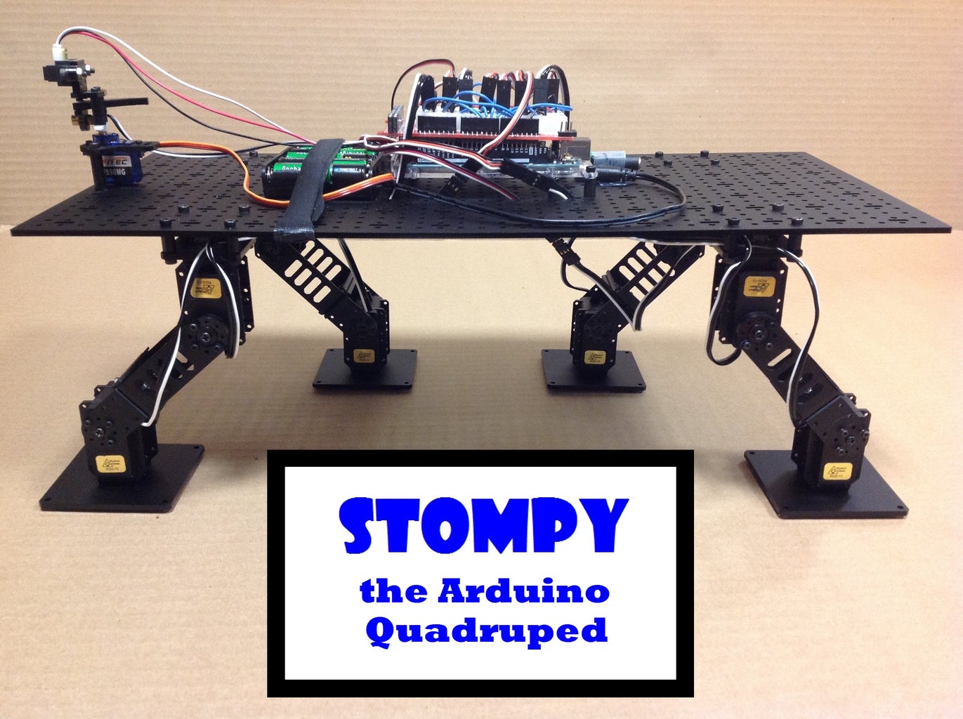


Meet Stompy, the Arduino quadruped robot.
Most of the quadrupeds I’ve seen use “insect” type legs, but I wanted to try one with “mammal” type legs. The result was Stompy, a quadruped using eight servos, with each leg consisting of a hip joint and an ankle joint (no knee). Stompy uses a “trot” type gait where the front right leg is synchronized with the back left leg and these two limbs move in antiphase with the other two limbs. The result is a stomping type of walk, but it gets the job done. Controlling all the servos requires eight PWM pins and standard Arduinos only have six, so I decided to use an Arduino Mega. Stompy uses an IR distance sensor to keep from bumping into things and is capable of autonomous movement.
Step 1: List of Materials

Step 2: Robot Construction
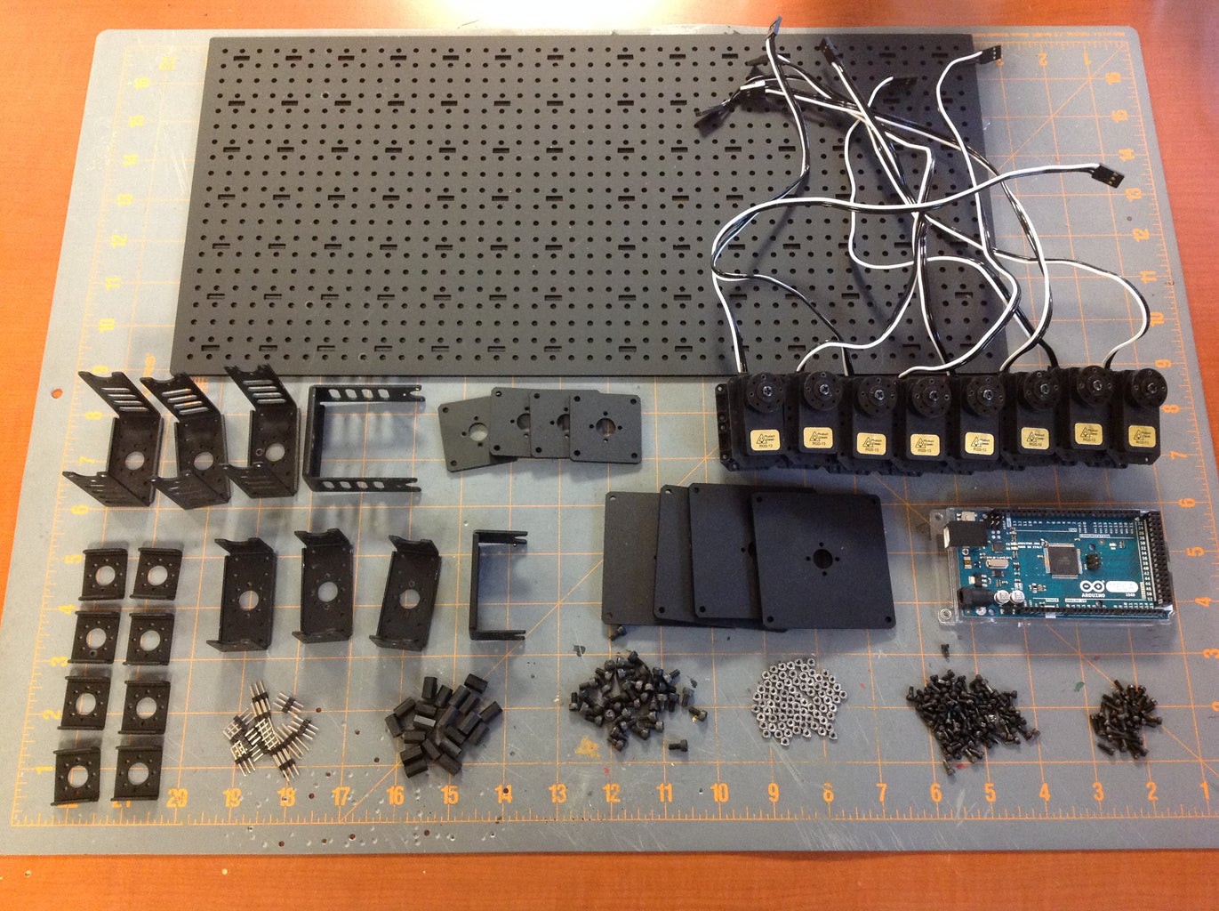
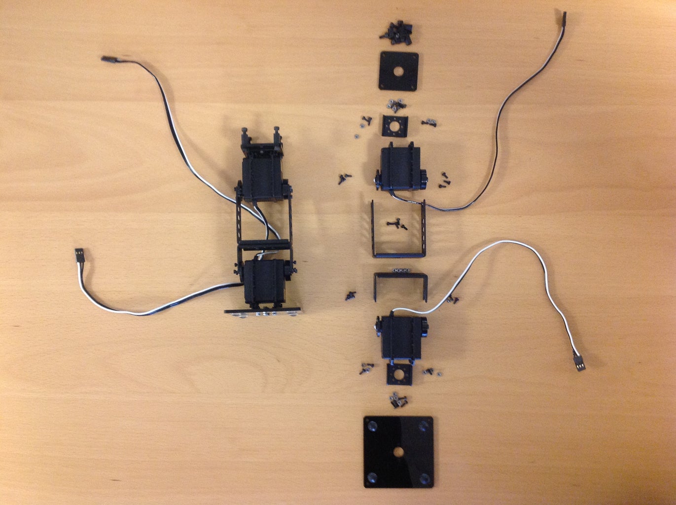

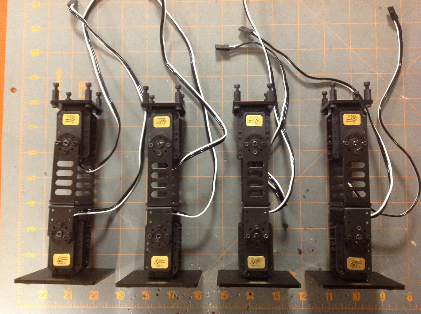
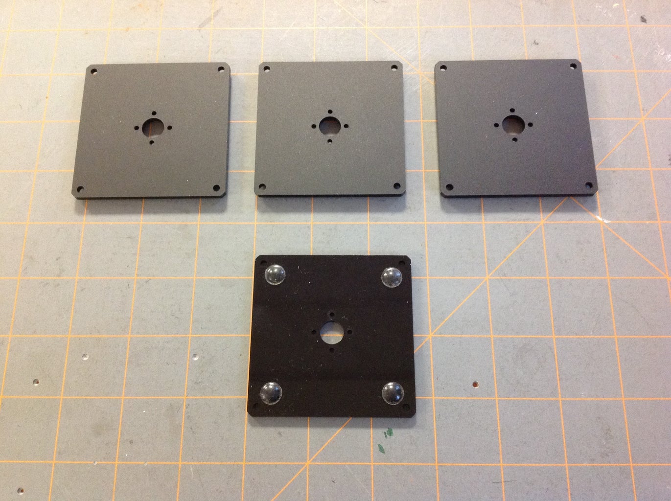
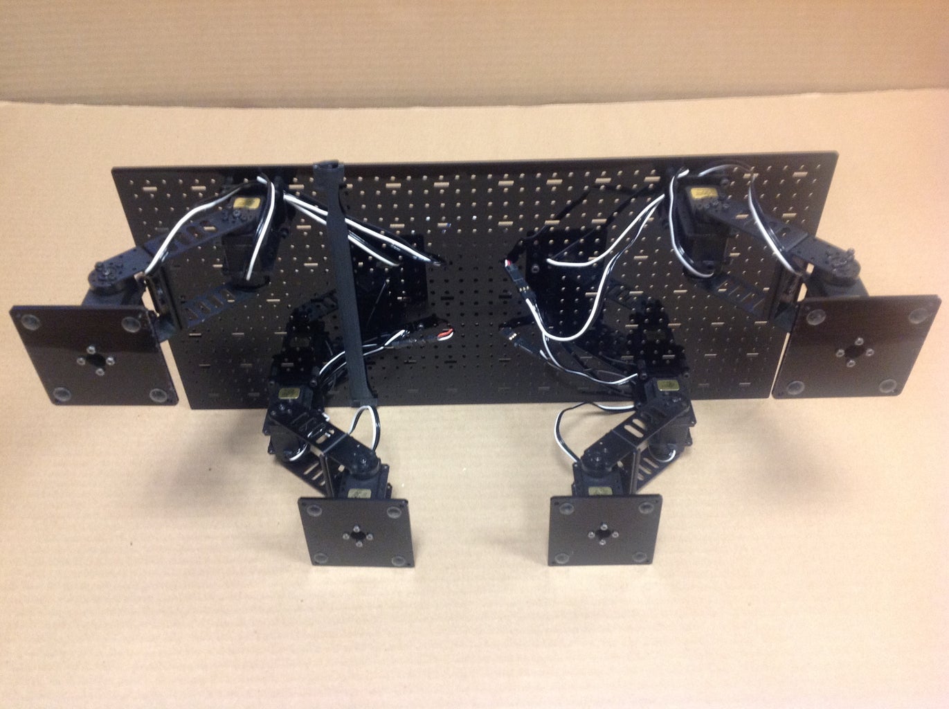

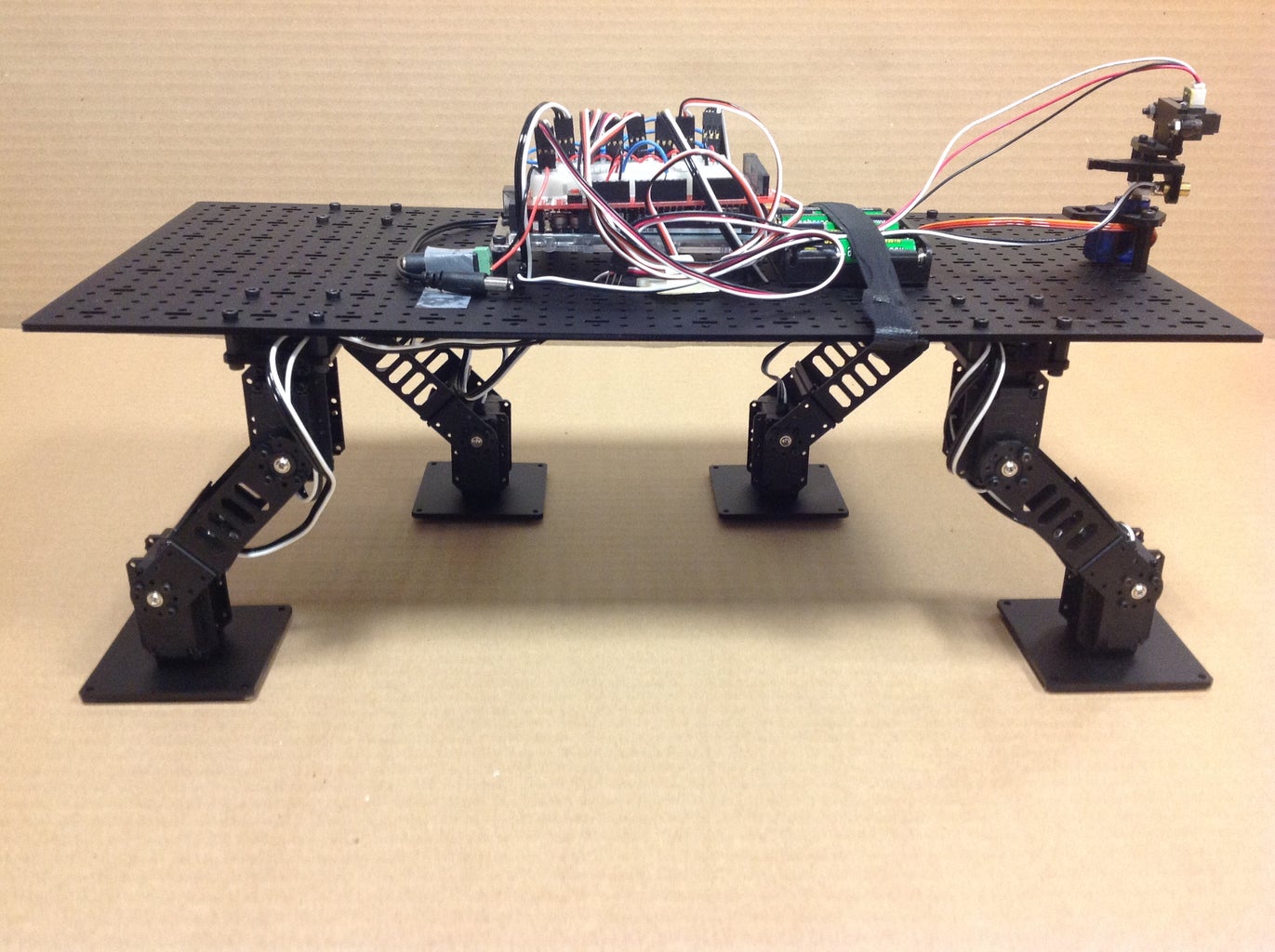
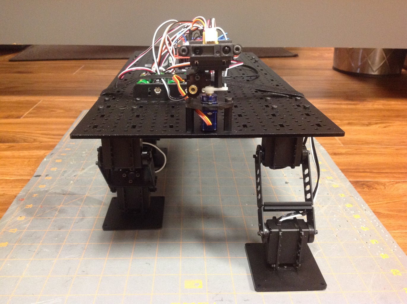
Leg assembly is illustrated in the photos above. For the robot to move properly, the servos need to be centered. Information on how to center the servos that I used is available here. The side bracket mounting kits I used came with two plastic plates. The larger of these worked perfectly as a foot for the robot. I placed four small adhesive rubber tabs in each corner of the plate to improve traction. These rubber tabs also provided clearance for the nuts and bolts that hold the foot in place. The four legs are then attached symmetrically to the large plastic platform that forms the body of the robot. The servo cables are passed through holes in the plastic platform and attached to the Arduino. The Arduino itself is also bolted to the plastic platform. An IR distance sensor attached to a micro servo forms the head of the robot. This allows Stompy to roam free range.
Step 3: Forward Movement
In the Arduino code given below, the movement of the limbs is controlled by the variable flex1, which sets the angle at which a limb is bent. I have it set to 45, but it can be increased or decreased to lengthen or shorten the stride. In the setup section of the code I initially position Stompy with the front left and back right legs set forward and the front right and back left legs set rearward. Writing a value between 0 and 90 to the hip servos corresponds to a forward position and a value between 90 and 180 corresponds to a rearward position. Since the ankle servos are aligned 180 degrees opposite to the hip servos, writing the same value to both the hip and ankle servos will result in the foot being parallel to the floor. The setup section ends with a 5 second pause to allow time to position the robot.
The loop section of the code contains the walking algorithm. First, I straighten the front left and back right legs. The variable smoothnessDelay controls the speed and smoothness of this motion. With the front left and back right legs now straight, the front right and back left legs are off the ground in the rearward position. I bring these legs forward in three steps. First, I flex the ankles all the way forward to get them as far off the ground as possible. Next I swing the hips forward, during which time Stompy's heels will skip the ground. Last, I level the ankles so that they are ready to hit the ground. Now, the front left and back right legs are moved to the rearward position. After this motion, Stompy is half way through one complete walking cycle. I now repeat the process with commands to diagonal pairs of legs switched.
Attachments

Step 4: Left Turn, Right Turn, Reverse
Stompy is somewhat less graceful when turning. Basically, to make Stompy turn, I make the stride on one side of his body shorter than the other. For example, to turn left I make the stride on the left side of the body one third as long as the stride on the right side of the body. The variable multiplier in the code controls this. It is a little awkward looking, but it gets Stompy from point A to point B. A right turn is accomplished in a similar manner. Reverse is a straightforward modification of the forward walking algorithm. The code for all three is contained in the attached files.
Step 5: Autonomous Movement
The four gait files given in the previous two steps, along with some distance sensor code, can be combined into one file to allow for autonomous obstacle avoiding movement. I use an IR distance sensor to measure the distance to obstacles in front of Stompy. If the distance is below a set tolerance, Stompy stops, looks to the left and right to take two more distance measurements, and then continues in the direction of the clearer path. Since Stompy cannot turn on a dime, the change in direction is accomplished by first backing up 3 steps and then turning in the clear direction for 5 steps. Stompy then continues forward in a straight line until encountering another obstacle. The number of steps in the change of direction sequence are controlled by the variables reverseTime and turnTime. I use a laser to indicate the direction in which Stompy is looking.
Attachments

Participated in the
Epilog Contest 8

Participated in the
Arduino Contest 2016


