

Introduction: Arduino RC Gamepad


I set out one day to figure out a way to utilize some relatively cheap electronics to make a homemade RC transmitter and Receiver using an arduino on both ends. The advantage of this setup vs a standard RC transmitter & receiver is that you can connect sensors to gain some level of semi-autonomous capabilities (for example a proximity sensor which takes over to stop the robot before it drives off the edge of a table or down stairs). You could also utilize more buttons on the gamepad to control other things besides the drive motors (like a gripper for example) without needing additional channels.
This instructable will show you how to build what I built which I consider a decent springboard from which you could build a more sophisticated project.
Step 1: What You'll Need

Parts
- [1] 433Mhz RF transmitter & receiver
- [1] gamepad shield
- [1] Arduino Uno R3
- [1] Arduino Pro Micro
- Male header row pins to solder to the Arduino Pro Micro
- [1] TB6612FNG dual motor driver
- [1] solderless breadboard
- [1] breadboard mount
- [1] 1/8" spacer (for breadboard mount)
- [4] 140RPM Right Angle Gear Motors
- [4] Motor Mounts
- [4] 2.55" Press Fit Wheels
- [1] 3.75" Aluminum Channel (585443)
- [1] Battery for Robot
- [1] Male XT60 connector (605138)
- [1] Battery for Transmitter
(I used an Electrifly BP910 because I had one lying around and it fits about perfectly into my controller. However the battery I used on the receiver end of things would work as well, and fits almost as good, and is much cheaper)- If you do use this battery then you will want a Male Deans Style Connector (605142)... to which you will probably want to just solder some jumper wires.
- Standoffs
- wires
- screws
- [8] 6-32 5/16" socket head screw (632108) for attaching motor mounts to channel
- [2] 6-32 7/16" socket head screw (632112) for attaching breadboard mount
- [6] 4-40 1/4” socket head screw (91251A106) for transmitter assembly
- [4] 4-40 3/16” socket head screw (91251A105) for transmitter assembly
- [6] 6-32 3/8” socket head machine screw (91251A146) for transmitter assembly
- [10] 6-32 nuts (585474)
- [2] #5 washer (90126A306)
Tools
- 3/32” Hex Key (7122A16) for 4-40 screws
- 7/64” Hex Key (7122A17) for 6-32 screws
#1 Philips Screwdriver
Step 2: RC Gamepad Assembly
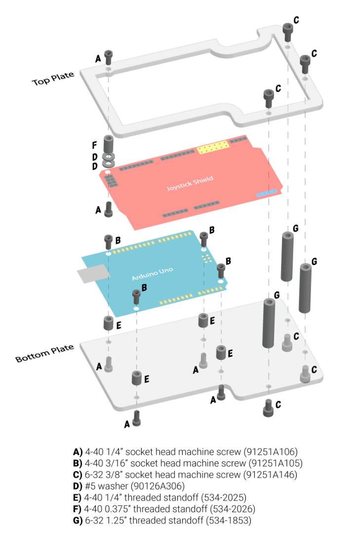

For the RC gamepad I laser cut a top and bottom plate out of 0.125" thick acetal and used standoffs to mount it all together. I created a diagram since I figured that would be the easiest way to show what went where.

Step 3: RC Gamepad Wiring


The wiring on the transmitter is very easy.
I plugged the VCC and GND pins of the RC transmitter into the + and – pins in the top right corner of the gamepad shield. This not only gave my transmitter power but provided a nifty way to mount it. I did need a jumper wire to go from the data pin on the transmitter to the D12 pin on the gamepad shield though.
The cavity just to the right of the arduino and below the joystick shield makes a nice spot for the battery.
Step 4: RC Gamepad Code
Step 5: Chassis Assembly


The chassis is very simple, it is comprised of a channel with 4 right angle gear motors attached (each with a wheel press-fit on the output shaft).
Step 6: Receiver Wiring


The wiring on this project gets a bit complex.
I used a 400 tie point solderless breadboard and detached the power rails so that it fits in the mini breadboard mount.
To keep you from spinning in circles or driving backwards when you first test it out I've provided a top-down view of the motors to help orient you. This assumes that you've mounted all the motors so that the solder terminals are facing inwards.
Step 7: Receiver Code
Step 8: Testing It Out
The only thing left to do now is test it out.
It does seem to suffer from some lag now and again and I believe this might be the arduino struggling to keep up with the constant stream of data coming from the transmitter. Hopefully I can build upon this for future projects and improve the performance. Feel free to contribute ;)
Step 9: Reference
I am only standing on the shoulders of giants.
Below are some resources I found useful to make this project happen.
- https://learn.sparkfun.com/tutorials/pro-micro--fio-v3-hookup-guide/hardware-overview-pro-micro
- http://www.embeddedrelated.com/showarticle/498.php
- https://www.instructables.com/id/Using-the-Sparkfun-Motor-Driver-1A-Dual-TB6612FNG-/
- http://bildr.org/2012/04/tb6612fng-arduino/
- https://www.pololu.com/file/0J648/TB6612FNG-dual-motor-driver-carrier-schematic-diagram.pdf
- https://www.pololu.com/file/0J86/TB6612FNG.pdf


