

Introduction: Arduino RGB LED Lamp + 4bit LCD Display


Before I continue. I do not go into details of how to cut the wood, or piece everything together. I freestyled the entire build process, whatever came to mind is what I reproduced. The point of this instructable is to be able to create the circuit, program the arduino, and create something of your own imagination.
Also this instructable is meant for people who are familiar with the ever so popular Arduino !!!
If you want to learn more about what the Arduino is all about please visit : Arduino Home Page
Alright now a little explanation what this exactly is. This is simply an arduino controlling an RGB LED to control lighting. There are 3 different modes. These modes can be selected by pressing a button. The Modes and values of the RGB are being displayed on a LCD screen.
Modes :
1) Hue Cycle : This cycles through the hue spectrum. You scroll the wheel (potentiometer) to control the speed at which the color changes from one to another.
2) Hue Selection : Scroll the wheel (potentiometer) to select the color you chose. IT remains at this color
3) Random Hue : The arduino randomly selects a target RGB color. It fades to that target RGB color. Then the process starts over again. You can select the speed at which the color fades from one to another
The following video is the creation of the Arduino controlled RGB LED Lamp from start to end.
Step 1: Materials
1) Arduino : decimila, freeduino, Rock Bottom Freeduino Kit (RBFK). (I used the RBFK because its cheaper and I was giving this away as a present.).
2) Potentiometer : Im using 120ohm but any will do in this particular application.
3) Push Button : Do not use a ON/OFF button. It must be a push button.
4) RGB LED : Make sure it is common cathode RGB LED's. Meaning 1 pin is GROUND and the other 3 pins R,G,B pins are POSITIVE.
5) HD44780-compatible LCD : From my best experience, all 16x2 LCD's I worked with are work with the 4bit library.
6) 5 x Resistors:
- 22ohm = LCD Contrast... *NOTE : Use a POT to determine best contrast for LCD.
- 2.2Kohm = PushButton
- 3 more resistors. You need to determine the values depending on your RGB LED. Details below.
Step 2: Circut Connections
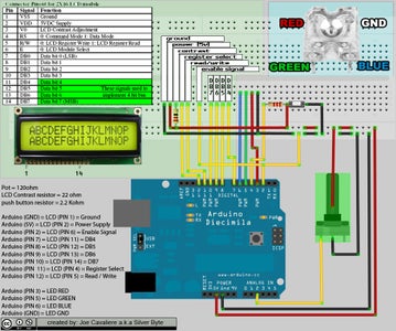
General Info & Tips
- make sure LCD (RW / PIN5) is hooked to ground.
Theres a mistake in the diagram I made below, it shows LCD PIN 6 is attached to GROUND.... thats wrong, LCD PIN5 is supposed to be attached to ground
- When testing LCD use POT to figure out proper resistence for LCD CONTRAST. You may think LCD isn't working when in actuality the contrast is just to low and you cannot see anything.
- NOT ALL LCD's are made the same. Refer to your LCD specs (google model # of LCD) for pinouts. (DB0-DB7, RegisterSelect , ReadWrite, Enabled, etc)
- RGB PINs needs a proper resistors for each color. The resistor is determined by the amount of voltage each color requires.
Eaxmple:
R = 2.8 - 3.2 volts = 82ohm (recommended)
G = 3.2 - 3.5 volt = 68ohm (recommended)
B = 3.2 - 3.5 volt = 68ohm (recommended)
use following URL to determine resistance for each color. LED series/parallel array wizard
Component Info
Potentiometer (POT) = 120ohm
LCD Contrast resistor = 22 ohm
push button resistor = 2.2 Kohm
LCD Connections
Arduino (GND) = LCD (PIN 1) = Ground
Arduino (5V) = LCD (PIN 2) = Power Supply
Arduino (PIN 2) = LCD (PIN 6) = Enable Signal
Arduino (PIN 7) = LCD (PIN 11) = DB4
Arduino (PIN 8) = LCD (PIN 12) = DB5
Arduino (PIN 9) = LCD (PIN 13) = DB6
Arduino (PIN 10) = LCD (PIN 14) = DB7
Arduino (PIN 11) = LCD (PIN 4) = Register Select
Arduino (PIN 12) = LCD (PIN 5) = Read / Write
RGB LED Connections
Arduino (PIN 3) = LED R = 2.8 - 3.2 volts = 82ohm (recommended)
Arduino (PIN 5) = LED G = 3.2 - 3.5 volts = 68ohm (recommended)
Arduino (PIN 6) = LED B = 3.2 - 3.5 volts = 68ohm (recommended)
Arduino (GND) = LED GND
Button & Pot Connections
Arduino (ANALOG PIN 2) = POT (wiper : usually in the middle, depends on pot)
Arduino (PIN 4) = PushButton (make sure to use 2.2Kohm or higher resistor)
Step 3: Arduino Source Code + Files
The Source Code, How to wire everything and LCD library are all contained in the Zip File.
Almost all the code was written by myself although I must add credit to the following code which I used.
Arduino Hue Function
select different Modes with push button
The hue function was extremly convienient, why reinvent the wheel.
As for the push button, you wouldn't believe how tricky this can be. This code was extremely helpful to use the pushbutton as I intended. (pressing pushbutton allows you to select different modes)

Step 4: Final Words
This project was created as a gift for a very good friend, and now I wish to offer this gift to the rest of the INSTRUCTABLES enthusiasts. This entire process was extremely an amazing experience and Im more than happy to share it with the world.
OH AND PLEASE DON'T FORGET TO VOTE !!!
Participated in the
Craftsman Workshop of the Future Contest
Participated in the
Homemade Holidays: Holiday Gifts


