

Introduction: Arduino Remote Control Lights With Universal Remote

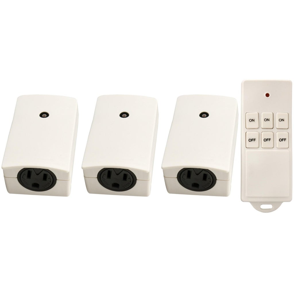
I have been looking into home automation for some time, but haven't committed to it just yet mostly because of the price tag. Last year (2010) I bought these remote control outlet on/off switches so I could turn my xmas tree lights on and off via remote for about $20 (USD). Here is a link to them on Amazon:
http://www.amazon.com/Woods-13569-Wireless-Control-Outlets/dp/B003ZTWYXY/ref=sr_1_2?s=hi&ie=UTF8&qid=1329628216&sr=1-2
What to do with them the other 11 months out of the year? I know! I'll plug them into lamps! Still, it wasn't exactly what I wanted just yet...
I wanted to expand their functionality and useability (mainly I just wanted to get rid of some of the multitude of remotes I had in the living room). I soon found out that they were controlled by Radio Frequency (RF). I decided to incorporate them into my universal remote control, but the remote only works using infrared (IR).
It's time to tear something apart and create something new out of the pieces!
Step 1: Gather Your Stuff!

First, you need to gather up all of the tools and items that are necessary for the project.
Arduino (I have an Arduino UNO r2)
Remote control from a RC outlet
Universal remote control (I used the Logitech 1100)
Wire clippers
mini breadboard
some 22 gauge wire
soldering iron
solder
6 NPN transistors
1 IR Receiver module
1 IR Transmitter module (optional for programmable remote)
project box (optional - I used a hollowed out book)
Needle nose pliers (optional, but always helpful)
Exacto knife (or some cutting utensil - not pictured)
Book (optional - not pictured)
Step 2: Open the RF Transmitter


Taking apart the RF Transmitter:
Removing the battery panel on the back of the remote control that came with your outlets and then removing the 1 screw inside. Use a flat-head screwdriver or something similar to pry open the plastic case.
Step 3: How Do You Activate the Receivers Manually?


Time to figure out what is going on inside this little remote so that I can think of ways to utilize it to suit my needs.
Let's find out how these buttons are seated on the board. A button has 4 legs (one on each corner of the button) that are individually soldered on the back side of the board. Taking a small jumper wire, I tested each pair of solder points under a single button until one of the outlets was activated. SUCCESS!! Continue with this process for each button, until you have the entire set of 6 buttons mapped out and written down or recorded somehow. Writing down the polarity will also help later on.
Tracing the charge through the board gets a little easier if you notice that the section of the battery holder with the spring is the negative side of the battery.
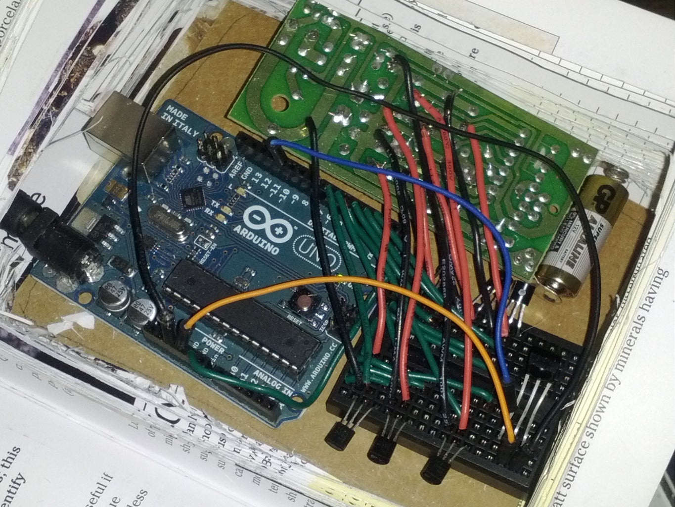
Step 4: How Do I Simulate Pressing the Button on Demand?

I knew that I wanted to somehow simulate pressing the button on the RF Transmitter, but didn't know how yet. I realized that I could solder some jumpers onto the button solder points, then send a HIGH signal through the Arduino digital pins to simulate the pressing of the button on the RF Transmitter (completing the circuit).
**NOTE: After you send a HIGH signal, you MUST send a LOW signal (to simulate the button depress action...your finger letting go of the button after pressing it). This will be commented in the Arduino sketch.
In this case, the transistors are acting as switches. Don't be intimidated if you don't know what that means just yet. I had to do a lot of Googling before I even knew that was what I needed, then I had to research even more to see what the heck it meant! It easily took me a few hours to figure out how a Transistor works, NPN or PNP, MOSFET, or any other transistor.
And now, onto the Arduino sketch!
Step 5: Program Your Universal Remote (optional)


Next, program your universal remote using your IR Transmitter module. I say that this part is optional, as you can always find the codes for devices that you don't have an just use those instead of programming your own. As it turns out, I do not own any Sony devices so I just used some device codes for Sony. I would suggest looking into the class and finding the best protocol for your own setup if you are recording your own IR.
The IRRecv class from Ken Shirriff's blog is an excellent reference and resource. I used the IRSendDemo to manually program my Logitech remote.
Ken Shirriff's blog: http://www.arcfn.com/2009/08/multi-protocol-infrared-remote-library.html
This is a simple setup. Wire the negative lead of the IR Transmitter to the ground on the Arduino through a resistor of appropriate value. For me, a 100ohm resistor was enough for the job. The positive lead will be wired to the digital PIN 3 on the Arduino (this is default for the class).
Step 6: Arduino Sketch

And now it is time for the coding, which was a LOT easier than I expected. I realized that I only needed to send a HIGH signal through one of the digital pins as a WRITE in order to complete the circuit if wired to the Arduino ground! To "stop pressing the button" you then have to WRITE a LOW after the HIGH is written.
//Arduino RF to IR project
//by Jack Zaldivar
//Send high signal (250ms) every 5 seconds, as test scenario
#include <IRremote.h>
//define Pin outs based on the layout of the original remote
const int OFF1_PIN = 2;
const int OFF2_PIN = 3;
const int OFF3_PIN = 4;
const int ON1_PIN = 5;
const int ON2_PIN = 6;
const int ON3_PIN = 7;
int BASE_PIN;
//the following section if for IR processing
int RECV_PIN = 11;
char* recv_IR;
IRrecv irrecv(RECV_PIN);
IRsend irsend;
decode_results results;
//during the setup() function; define all pins as OUTPUT except the IR Receiver, which will be an INPUT
//This will also turn all OUTPUT pins to low by default
void setup() {
//Define all ON Pins and set mode to LOW
pinMode(ON1_PIN, OUTPUT);
digitalWrite(ON1_PIN, LOW);
pinMode(ON2_PIN, OUTPUT);
digitalWrite(ON2_PIN, LOW);
pinMode(ON3_PIN, OUTPUT);
digitalWrite(ON3_PIN, LOW);
//Define all OFF pins and set mode to LOW
pinMode(OFF1_PIN, OUTPUT);
digitalWrite(OFF1_PIN, LOW);
pinMode(OFF2_PIN, OUTPUT);
digitalWrite(OFF2_PIN, LOW);
pinMode(OFF3_PIN, OUTPUT);
digitalWrite(OFF3_PIN, LOW);
Serial.begin(9600); //Open Serial port and set data rate
irrecv.enableIRIn();
}
void loop() {
if (irrecv.decode(&results)) {
/*
//Uncomment these next few lines and monitor the values in the Arduino Serial monitor to view debug data
Serial.print("bits: ");
Serial.println(results.bits);
Serial.print("type");
Serial.println(results.decode_type);
Serial.print("ul value: ");
Serial.println(results.value);
Serial.println("---------------------------");
Serial.println(ultoa(results.value, NULL, results.bits));
unsigned long test = strtoul("a90", NULL, 12);
Serial.println(test);
*/
if (results.value == 2704) //piano Light ON - Light 1
{
processReceived(ON1_PIN);
}
if (results.value == 2705){ //piano Lamp OFF - Light 1
processReceived(OFF1_PIN);
}
if (results.value == 2706){ //Table Light ON - Light 2
processReceived(ON2_PIN);
}
if (results.value == 2707){ //Table Light OFF - Light 2
processReceived(OFF2_PIN);
}
irrecv.resume(); // Receive the next value
}
}
void processReceived(int BASE_PIN) {
digitalWrite(BASE_PIN, HIGH);
delay(1000);
/*
Serial.print lines are only used for debug purposes. Uncomment if you need to view the status of the function
Serial.print("Wrote ");
Serial.print(BASE_PIN);
Serial.println(" HIGH");*/
digitalWrite(BASE_PIN, LOW);
/*
Serial.println("Wrote LOW");
Serial.print("Processed: ");
Serial.println(BASE_PIN);
*/
}
Step 7: Disguise Your Creation to Fit in Your Space


In order to use my creation I now had to make it pretty, or at least hide it somehow.
Enter the hollowed out book idea! A classic!
I found a very inexpensive book at a local Half Priced book shop and hollowed it out using an exacto knife and a LOT of patience.
Next, I mounted the Arduino to a piece of cardboard that I cut from a 12-pack box of soda, using Command strips. I did this so the components wouldn't move around in the book when placed inside.
Seat the cardboard mount behind the last page that you hollowed out and measure (eyeball it) where you will need to cut the pages so that you can still plug your board into power.
Next, take your exacto knife and make an opening for the power cables.


