

Introduction: Arduino Robot Arm


Arduino robot arms are among the most popular DIY projects. We decided to make ours out of recycled materials we found in our workshop. We hope you enjoy this build.
Step 1: Electronics

Main components
Arduino UNO3
SparkFun Servos (Generic Metal Gear)
PS2 Joystick 2 axis module
Secondary components
Voltage Regulator 5v
Electrolytic Capacitor - 1uF/50V
Capacitor Ceramic 100nF
HeatSink TO-220
BreadBoard - Half Size
Jumper Wires Pack - M/M
See the wiring diagram, or click here
Step 2: Code
- First, you’ll need to download the circuit code from the code tab on circuito.io.
- Follow the steps to check that you wired it correctly
Replace firmware.ino test code from circuito.io with the firmware.ino code in this Github repository. Leave the other libraries as is.
Make sure to leave "Include Libraries" and "Pin definitions”. Check that the pin definitions match.
Step 3: Materials
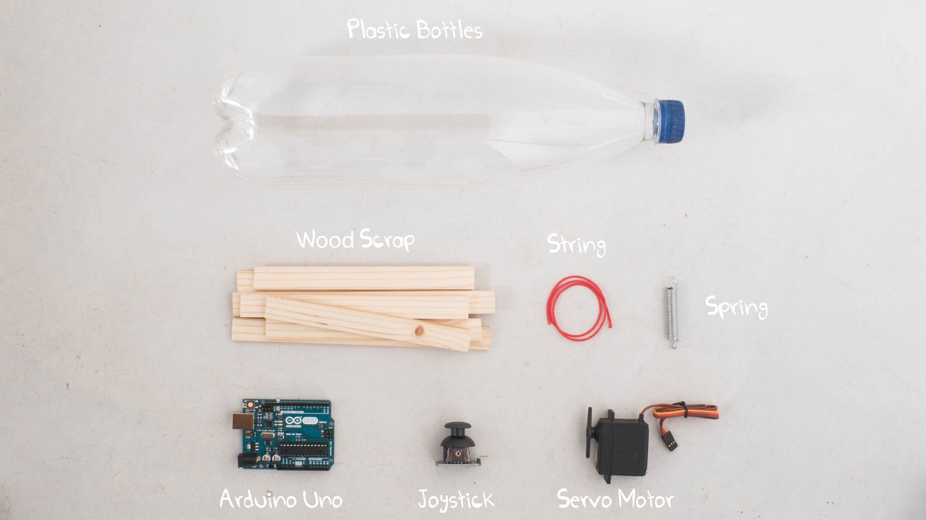
- We used 1cm-thick wood scraps we had in our workshop. In some places, we glued 2 pieces together for extra strength and robustness. You can check for other materials you have around you but make sure that it’s sturdy yet flexible.
- For tying the parts together we made heat-shrinks out of plastic bottles . It’s an awesome technique that you can make with plastic bottles you have at home. Play around and test these a little, you’ll be surprised how strong they are.
- The arm moves in 3 axes, therefore we’re going to use 3 servo motors.
Step 4: The Base

Start the build with a solid base so that the arm doesn’t tip over. At the same time we also need to understand what would be the best way to bind and tie the pieces of wood together so that the base is solid. In the image below you can see the way we used the heat-shrinks and a potato (!) as a base as the weight. Just don’t forget to replace it from time to time :)
Step 5: Balance

Placing the second servo was more tricky and we feel that this area still needs some attention. We realized, after building the prototype, that we hadn’t given enough thought to balancing the upper arm. Therefore, the servo motor draws a lot of current - something that can be overcome by using a counterweight on the opposite side of the arm.
Step 6: The Gripper

There are different types of grippers we considered, and we weren’t really sure what we're going to do here. Eventually, we decided to make one side of the gripper static so that it will have a strong grip. As you can see in the image below, for the moving part we made a joint, that is controlled by the servo and added a spring for closing and opening.
Step 7: You're Done!

At last, we placed some string inside an elastic tube to connect between the servo motor and the gripper, the same mechanism that you can find in bicycle brakes.
That’s basically it! You’ll probably need to make minor tweaks and changes to the code and mechanics according to the material and electronics you use. If you have any insights or comments, we’d love to hear them! Share them with us on our forum or in the comments below.


