

Introduction: Arduino Robotic Arm


Since it’s my first project after the 15 tutorials of my Arduino starter kit, the real purpose of it is to get some critics, tips, suggestions, ideas from anyone who knows more than me.
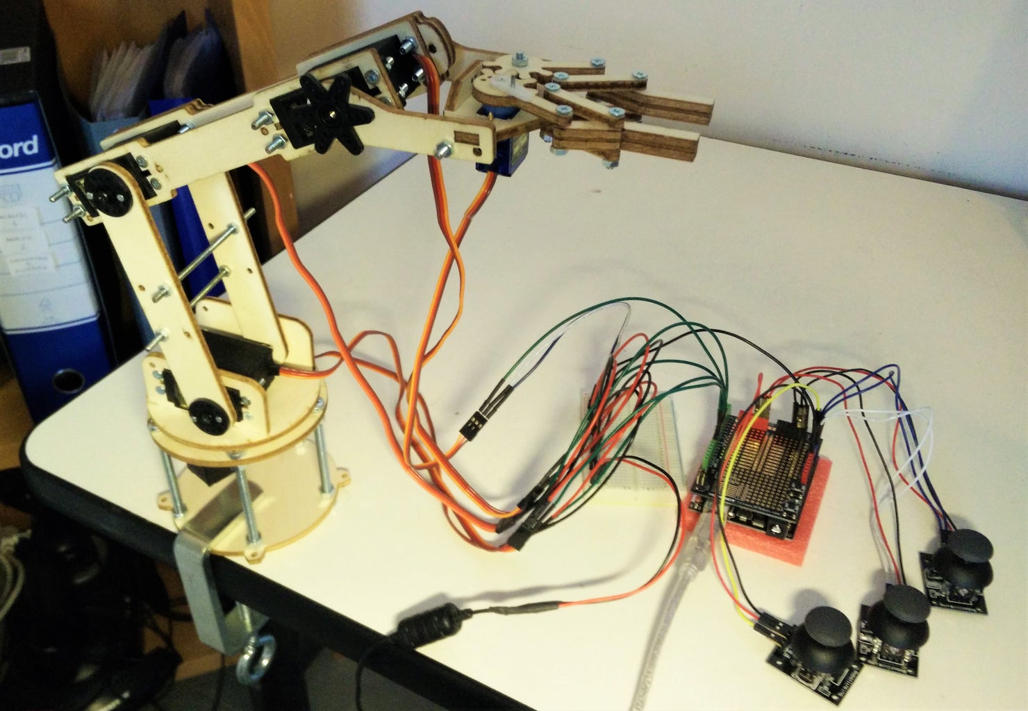
This project is about a robotic arm, with 4 dofs and a grip. With a decently low budget: the structure has been cut by a friend, the 4 servos were 30€, the 2 joysticks 4€, bolts screw etc. for less than 10€ and all the rest (Arduino, wires, grip’s servo etc.) was already included in my starter kit. For a total of 40-45€ which are about 45-50 US dollars (the same price of a me-arm kit, but hey, it was fun to have to build it by myself (and mess something up once in a while) and not following instructions like a machine).
Since this was my first project and Instructable, i entered the ''First Time Author'' and a couple other contests, so if you like it, vote it :)
Step 1: DESIGNING AND ASSEMBLING:
First I needed a structure:
This was definitely the longest part.
Since I didn’t want to copy and paste the project from someone else, I took a project as reference and I (and a couple of more skilled classmates who really saved me) started to modify it according to our needs (different servos with different torque, weight and dimensions, etc.). I had to build it a few times, each one of them I found something wrong, and we had to recut some pieces and retry.
I have attached the .dxf file in case you want to use it.
Then I had to buy the electronics:
Most of the parts were standard, the hard part was to choose the servos. I calculated the required torque with the rule of thumb, later on I tried a more accurate calculation and I found out that I might have overkilled it a little.
Apparently 6 kg/cm would have been enough for the 2nd servo (from the base), and mine provides 9-11 kg/cm. Well, this gives me some safety and the chance to load up to 2kg of load (which is impossible, but I like that I could technically do it).
I could have also bought different servos, with decreasing torque while moving away from the base, but buying identical servos from the same vendor was by far the cheapest option.
Power supply:
The Arduino was definitely not enough for the servos, since each mg995 draws 350mA and the microservo 9g draws 100mA, for a total of 350*4 +100 = 1500mA. So I salvaged a charger (6V 1.5A) and soldered two jumper wires to it.
(if some of you might need some real instructions, just ask in the comments, and I’ll do my best to create a step-by-step guide)
List of materials:
- Structure
- M5x7cm screw x5, m5 bolts x15 (base)
- M3x16mm screw x18*
- M3x20mm screw x13*
- M3 bolts x40*
- M3x8cm screw x3
- Clamp (otherwise it will fall)
- 3 dowels
- Arduino (or something else to control it, it has to have at least 5 PWM)
- Something to supply 5-6V and at least 1.5A
- 3x ps2-like joysticks
- 4x TowerPro mg995 servos
- 1x TowerPro 9g microservo (for the grip)
- Lots of jumper wires
- Breadboard
*(I used bolts and screws to be able to assemble and disassemble quickly, otherwise you could replace almost all of them with woodworks screws)
Attachments

Step 2: CODE:
The idea is to control every servo with one of the two axis of a ps2-like joystick.
Every joystick seemed to have different “rest values” (the value between 0-1023 when it’s still) for both the y and x axis.
That was a problem, since the difference was all but small (one had the zero on y at 623) and I wanted to use the map function to convert from 0-1023 to degrees. But the map function thinks the rest value is 1023/2. Which brought to every servo moving as soon as I switch on the Arduino, not good.
I managed to get around this by finding manually the difference between the reading value and each different rest value (which I calculated separately for every joystick), then to make the code shorter and smarter, I made him read the rest values in the setup function and save them in some variables.
The new algorithm relies on converting the increment in degrees, but I wanted a very low amount of degrees for my increment, so I had to divide it for a constant: I tried many values, until I came up with the final 200 (I may add a potentiometer to manually change this value to the desired one).
The rest of the code is pretty standard I guess, even though it might be more elegant to put the calculation of the increment inside a separate function.
Attachments
Step 3: ELECTRONICS:

The wiring is the same as shown in the picture or the fritzing file:
servos signal to pins: 5-6-9-10-11 and joystick axis to analogic pins: A0-A1-A2-A3-A4
The major problem I ran into was that the joysticks HAD TO BE supplied by the Arduino, NOT by the charger I use for the servos. Otherwise the servo would just go crazy moving randomly back and forth.
I think that might be because, if I supply them with the charger, the Arduino won’t be able to precisely tell the potential difference when I move them, but then again: I’m very new to electronics so it’s just a guess.
Connecting the Arduino ground and charger ground through the breadboard helped preventing random and unexpected movements, for a similar reason of the joysticks supply I suppose.
Attachments
Step 4: CURRENTLY GOING ON IMPROVEMENT:

Since every joystick can control 2 servos (1 per axis), I need 3 servos to control the whole arm, but unluckily I only have 2 thumbs.
So I thought that, instead of controlling every servo, I could control only xyz position of the grip and open-close the grip, for a total of 4 axis, 2 joysticks and 2 thumbs!
I found out that that problem is well known as Inverse Kinematics, I also found out that it’s all but easy.
The idea is to write (nonlinear) equations to find the state of every effector (angles for the servos) given the final position.
I’ve uploaded a hand-written paper with the equations, and I’m currently working to a new code to use them. It shouldn’t be too hard, I basically have to read the joysticks, use their readings to modify the xyz coordinates of the grip, and then give them to my equations, calculate the servos angles and write them.
Step 5: FUTURE IMPROVEMENTS:
So, I’m pretty satisfied with the outcome of it and considering that I’m totally new to electronics not blowing something or myself up was already a huge victory.
As I said at the beginning, any idea for future improvements, both software and hardware, is more than welcome!
So far I thought about:
1. The potentiometer to modify the “sensibility” of the joysticks.
2. New code to make him “record” some movements and do them again (maybe faster and shorter than the human input)
3. Some kind of visual/distance/voice input and being able to get objects without someone using the joysticks
4. Being able to draw geometrical figures
Any other idea? Please feel free to comment with any suggestions.
Thank you

Participated in the
Robotics Contest 2016

Participated in the
Make it Move Contest 2016

Participated in the
First Time Author Contest 2016


