

Introduction: Arduino Temp/Humidity With LCD and Web Interface


I recently helped a client move their office which included setting up a new computer room.
I wanted them to be able to check the temperature and humidity of the room both by checking an LCD display in the room and also via a web page. I put together an Arduino with a DHT11 sensor, 16x2 LCD display and ENC28J60 Ethernet module. I did the project in stages first getting the DHT11 portion working using the DHT11 library and examples from Adafruit, then adding an LCD display and finally adding Ethernet using the EtherCard library and modifying their example code . This makes troubleshooting a lot easier and I could build/learn the code as I went along. I have taken code from the various examples provided with the necessary libraries.
This instructable will go through the steps to prototype this.
Note: the DHT11 sensor isn't very accurate - about plus and minus 2 degrees Celsius and 5% accuracy for humidity. I'll probably be changing to a DHT22 which is plus and minus .5 degrees Celsius and between 2% and 5% for humidity. The good news is it's an easy change in the code.
Step 1:
- An Arduino
- DHT11 or DHT22 sensor from Adafruit or various ebay vendors
- 10K resistor for the DHT11 pullup
- 16x2 LCD display HD44780
- 10k trimpot for LCD contrast
- 100 Ohm resistor for the LCD backlight
- ENC26J60 Ethernet module or shield
- Prototype shield if you use a regular Arduino and ENC28J60 Ethernet shield
- hookup wire, breadboard etc for prototyping
Step 2: Wiring Up the DHT11


- +5v
- Signal
- not used
- GND
For this project the Signal lead goes to Digital Pin 2 on the Arduino
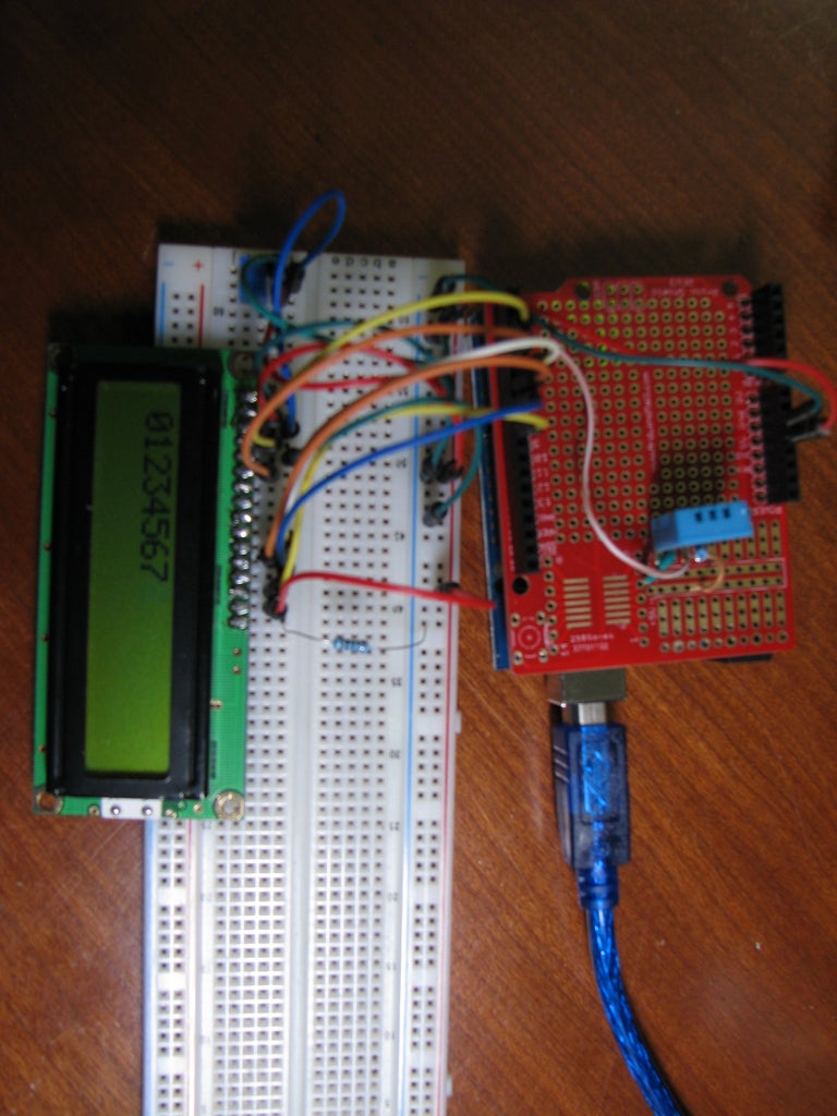
The images show the DHT11 soldered into a prototype shield with the signal lead going to the Arduino digital Pin2
Step 3: DHT11 Library and Test Sketch


- Download the library from Adafruit, the link takes you to the "GitHub" page. Look for the zip file download button.
- Unzip the files into your libraries folder. The best place to unzip to is under your "My Documents\Arduino\Libraries" folder - later if you upgrade the Arduino IDE the library will still be there.
- If you browse to your libraries folder you should see a new folder named DHT-sensor-library-master Rename it to DHT
- Connect up your Arduino and start the IDE
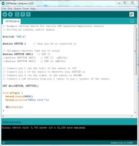
- Look under File -> Examples -> DHT and open DHTtester.
- You will need to comment the line startng with #define DHTTYPE DHT22 by putting a // in front of it and then uncomment the line starting with //#define DHTTYPE DHT11by removing the two leading//'s.
- Upload the sketch then open the serial window. You should see the temperature and humidity level scrolling. If you breathe onto the sensor you should see the temperature and humidity rise. It will take a few seconds as the sensor is slow.
Find the lines:
float h = dht.readHumidity();
float t = dht.readTemperature();
and change them to:
int h = dht.readHumidity();
int t = dht.readTemperature();
Upload the sketch and check the results in the serial window. You should see the temperature as whole rather than decimal numbers.
If you have a working sensor the next step is to connect an LCD display and see the temp and humidity on it.
Before you go onto the next step you should save the sketch to a folder. This way if you need to troubleshoot later you can load the minimal code needed to test the sensor.
My test sketch:
Attachments

Step 4: Wiring Up the LCD


The LCD has 16 pins, 12 are used.
Pin1 to Ground
Pin 2 to +5V
Pin 3 to 10K trimpot center
Pin 4 (RS) to Arduino Digital Pin 3
Pin 5 (RW) to Ground
Pin 6 (E) to Arduino Digital Pin 4
Pin 7 - Not Used
Pin 8 - Not Used
Pin 9 - Not Used
Pin 10 - Not Used
Pin 11 (D4) to Arduino Digital Pin 5
Pin 12 (D5) to Arduino Digital Pin 6
Pin 13 (D6) to Arduino Digital Pin 7
Pin 14 (D7) to Arduino Digital Pin 8
Pin 15 (Back Light +) to 5v
Pin 16 (Back Light -) to ground via100 Ohm resistor)
One side of the 10K trimpot goes to +5v the other side to ground
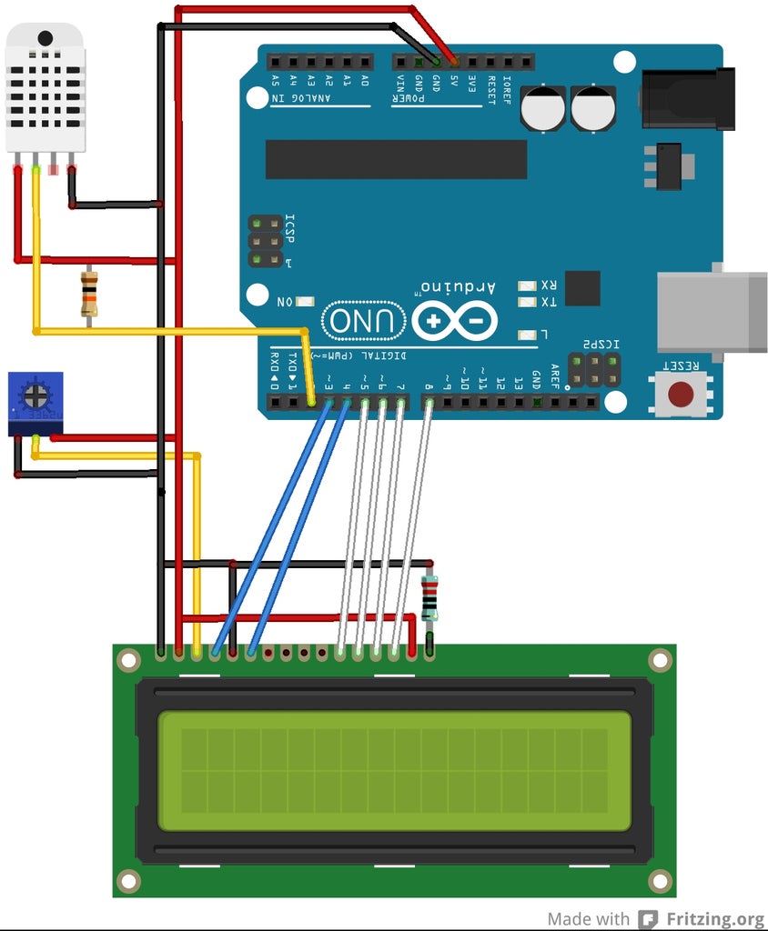
See the schematic diagram and pictures.
Note I have flipped the Arduino upside down in the "Fritzing" schematic to match the photo's and make the wiring neater.
Step 5: LCD Test Sketch
- Open the "HelloWorld" test sketch under File -> Examples -> LiquidCrystal
- Look for the line:
and change it to:
LiquidCrystal lcd(3, 4, 5, 6, 7, 8);
We need to change the pin assignments as the Ethernet controller we will add later uses pins 11 and 12
- Upload the sketch
- Adjust the trimpot until you see the display clearly
- You should see hello, world! on the top line and numbers counting on the second line
- Save the sketch to a folder.
It also covers the lcd.begin, the lcd.print, and the lcd.setCursor
Attachments
Step 6: Combining the DHT11 and LCD Sketches
If the DHT11 test sketch and the LCD test sketch both work we can combine them.
Load the sketch below.
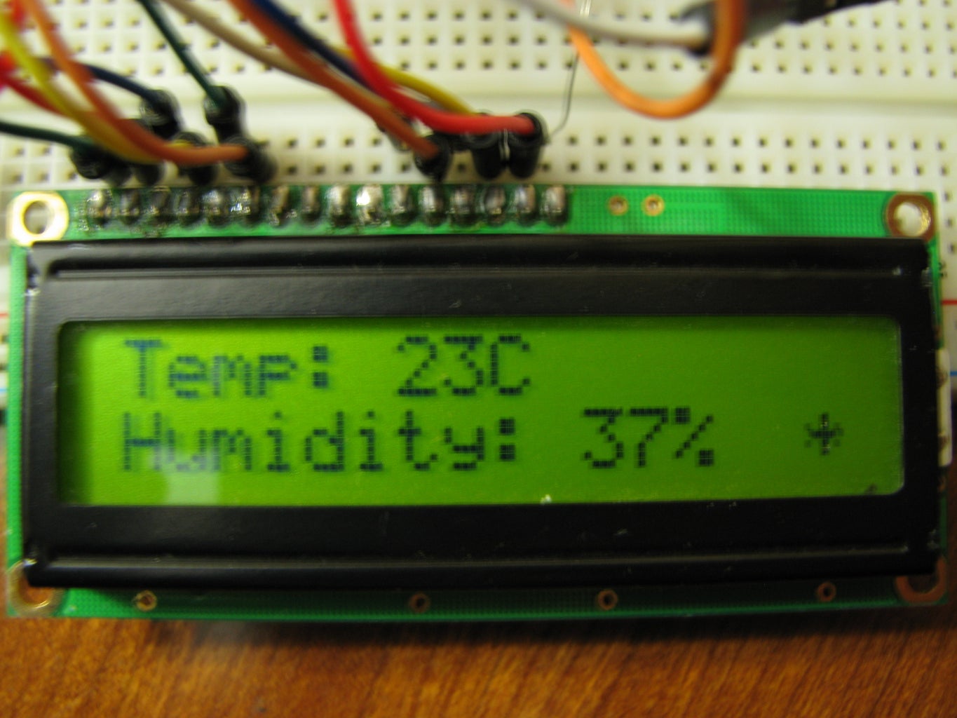
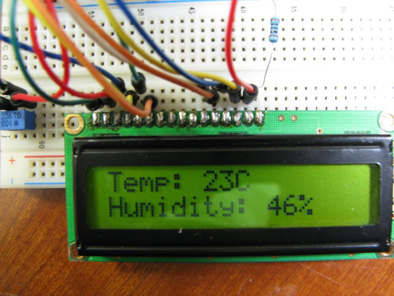
Upload it to the Arduino - you should now see the temperature and humidity displayed on the LCD screen.
Again, breathe on the sensor and you should see the temp and humidity change.
If this is working save the sketch and we can move onto setting up the Ethernet.
Attachments
Step 7: Wiring Up the ENC28J60 Module


I am using an ENC28J60 module for my prototype.
You need to supply 3.3V to this unit.
The pins we use on the module are:
VCC, GND, CS, SO, SI, SCK
VCC to Arduino Pin 3.3V
GND to Arduino Pin GND
CS to Arduino Digital Pin 10
SI to Arduino Digital Pin 11
SO to Arduino Digital Pin 12
SCK to Arduino Digital Pin 13
The last thing to do is connect a Cat5 patch cable from the RJ45 port to a spare port on your network router or switch.
Step 8: ENC28J60 Test Sketch and Library

Like the DHT11 we need to download ans install a library for it as it is not the "official" Arduino Ethernet module (the WizNet W5100 is). The old library for the ENC28J60 is called EtherShield and development has stopped for this library. The new library is called EtherCard and is available on GitHub.
Like the DHT11 library you need to:
- Download the zipped file and then unzip them into your library folder
- Rename the folder to EtherCard.
- Restart the Arduino IDE so the library will be included.
- Load the example sketchrbbb_server
- Look for the line starting with - static byte myip[] and change the IP address to a unused IP address on your network.
- Look for the line:
and change it to:
if (ether.begin(sizeof Ethernet::buffer, mymac, 10) == 0)
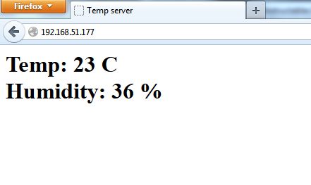
Upload the sketch then open a web browse on your PC and go to the IP address you specified in the above address. You should see a timer counting.
If it work then you may want to try some of the other example sketches included with the library. Just make sure you add the 10 to the ether.begin line as noted above.
Attachments
Step 9: Tying It All Together
My first attempt at tying the 3 test sketch's together worked, however the Ethernet would often timeout. So I got some help from Kev_MacD who helped me modify the sketch to get better timing in my loops.
The posted sketch has comments in it:
We added a gateway IP address as I want to be able to view the webpage from outside the LAN - you will need to do port forwarding on your router to make this work.
We define global variables for the temp and humidity values
We define variables for 2 timers, one for the sensor read time and one for an animation on the LCD
The "refresh" value in the webpage code was changed from 1 to 30 to make the refresh 30 seconds vs every second. This line could be removed if you don't want the page to auto refresh or increased to make the refresh time longer.
Upload the sketch, open a web browser and go to the IP address. You should see the temperature and humidity the same as what's on the LCD display. The LCD should also have an animation showing on the bottom right of the display.
In future version I hope to change the LCD to a 1.8" TFT colour display with an NTP clock so I can see the timw, temp and humidity on a larger easy to read screen. I welcome comments and feedback on this Instructable.


