Introduction: Arduino - Theremin With 7 Segment LED Display


The basic idea was to use a LED display programming by Arduino that can display some character with various intensity of flash. Then I saw some Theremin Instructables using Light sensor that made a unique sound when it given the light. Then the idea to combine the both project really made me excited.
This project was made for my own project on campus. It is built since 3 months ago, so there will be some different picture for one part, because it's been fixed from time to time, and continues to have a progress.
This circuit it's so simple, but the process requires patience, precision, and efficiency.
This is the video of my Arduino - Theremin with 7 Segment LED Display
(change the quality for a better view)
Okay, let's get started.
Step 1: Parts and Tools


Here is all you will need:
(1) Arduino UNO R3
(1) 10K potentiometer
(21) LEDs (White, Red, Green, Blue, Yellow)
(2) Push Button
(1) LDR (Light Dependent Photo Resistor)
(1) PCB Matriks / Perfboard
(1) Speaker 8 ohm (0,5 - 0,6 watt)
(2) 10uF Electrolit Capacitors
(3) 10K ohm resistors
(7) 100 ohm resistors
(1) 9V battery
(1) 9V battery box with on-off switch
(1) Potentio knob
(3) Spacer 0,5 cm
(4) Spacer 1 cm
(2) Spacer 2 cm
(1) Project enclosure
- Breadboard
- Shrink tubing
- Jumper wire
- Rainbow wire (optional)
- Male header extended (optional)
- Male header bended (optional)
- Blackhousing / female 1x1 header (optional)
Tools:
- Soldering iron
- Solder
- Hot glue
- Mini drill
- Pliers
- Cutter
- Helping hands (if you don't have it, you can build it from my helping hands instructable )
Step 2: Build the LED Display (Prototype)


This step is for Protoboard using. In this step you will need :
- (1) Perfboard (that enough for 21 LEDs)
- (21) LEDs (the colour combination is up to you)
- Jumper Wires
As I already said before, you can go to Enjoying Electronics's Intructables for more details information, specially for this step.
Each color has a specific wavelength, which can produce varying tones when received by the Theremin. That's why I use a different color LEDs instead of just use one type of LED colors.
Step 1
Place the LED on perfboard. Each segment will have 3 LEDs wired parallel with each other. Be careful with the negative and positive leads, the positives of these LEDs are all connected together in parallel. (See image 2)
Step 2
All the anodes of one row are connected together. There are 3 LEDs in one row. (See image 1). When you supply voltage to the row, the whole row will lights up.
Step 3
All the grounds will be connected together.
Step 4
Solder a quite long wire to positive lead of each row LEDs. (see image 4)
Step 5
Join all the negative lead of each row with a short wire. And solder once again with long enough wire. There will be 8 wires (7 wires for each row, plus 1 wire for ground) (see image 4)
Step 3: Making the Circuit on Breadboard


Let's build it on breadboard first. First, lets put the components on a breadboard so we could see how it worked and how to fit it onto the perfboard. The circuit diagram was made with Fritzing.
Step 1
- Add resistor 100 Ohm for each row
Step 2
- Add resistor 10 K and connect to positive / Vcc, it will be a pull up resistor for push button
- Add a capacitor 10uF, the negative lead connect to ground and connect to one of push button leg. The positive lead connect to other leg of resistor 10K and other leg of push button.
Step 3
- Put LDR series with resistor 10K, the other lead of resistor connect to ground. and the other lead of LDR connect to positive/Vcc.
- Put a jumper between meeting of the LDR and resistor, and connect to the A0 pin of Arduino.
Step 4
- Positive lead of speaker connect to pin 11 of Arduino
- Negative lead of speaker connect to GND of Arduino
Test everything out and make sure that you're circuit is going to work before you start soldering.
Step 4: Write the Code

I'm an Arduino beginner, but this code seems to be pretty good. But I'm not sure to answer your question about advanced programming. And the code that I attach here it's still for my project on campus, so you will see character "POLBAN" that's an acronym of my campus name, Bandung Polytechnic State.
You can play with the code for change the characters as you want. So you will have 2 different character display for push the 2 buttons. For the random flash (it's always looping if you're not push the push button), you can change the code to get a varying tone, because the distance of row LEDs to the LDR can cause a different tone, and also the color of the LED can affect the tone to be produced.
Note: you are somewhat limited in what letters you can display, such as capital R, Z,W,X, and others.

Step 5: Build 7 Segment LED Display (PCB Printed)


This step is for build on PCB Printed. Because it's should be done as soon as possible for my project on campus, I'm using a custom PCB (printed circuit board) from a manufacturing company. And it was cheap to get manufactured, the size are about 6 x 6,5 cm.
I'm using Altium Designer to create the PCB design. But you can use other software such Eagle, Protel / Proteus with the schematic that I already attach.
A PCB design for direct toner transfer is added too. The design is slightly different from the prototype shown in the pictures. There are a bit different route around the LEDs, because I can't find the first design of my PCB on my computer, so I should redesign it.
Step 1
Put the LEDs in order, the combination is up to you, but I like to do the combination as shown on image 3. The reason for the combination is that the green and blue LEDs are not intermingled with each other. I crossed them, and put red and yellow LEDs series with them in a row.
Step 2
Soldering them with carefully.
Step 3
Add resistors to the place. and soldering them with carefully.
Step 4
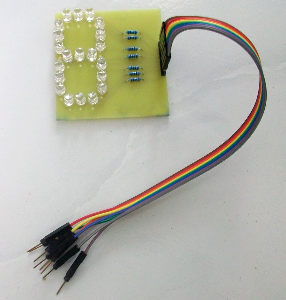
Soldering 8 male headers (extended) upside down, because we will attach the cables on the back of the PCB. And bend it a little (see image 4). This is for the efficiency.
Attachments

Step 6: Attach the Cables


Step 1
Create the cables. I'm using rainbow cable, because it's flexible and easy to remember because there will be one color for each row.
#For the Male side
*This side will connect right to the Arduino
- Strip the end of the cable
- Using a male header (bended)
- Solder it together and put on some shrink tubing / or cover with duct tape (like mine)
- Make 7 of these.
- For the ground I'm using just a male header (extended), you can see on image 1. The green one is for ground.
#For the Female side
*This side will connect to the male header on PCB 7 Segment LED Display. See image 3 to attach the wires in order.
- Using 8 blackhousing / female 1x1 header
Step 2
Connect the cable with the male header on LEDs PCB (see image 3)
- row 1 = brown
- row 2 = red
- row 3 = orange
- row 4 = yellow
- ground = green
- row 5 = blue
- row 6 = purple
- row 7 = grey
Step 3
Test every row with positive leads of the battery / power source 5V, and connect the ground cable to negative leads of power source.
Step 7: PCB Printed for Theremin Circuit


The second PCB is for Theremin circuit.
Step 1
Arrange the component, I usually place all components in before starting to solder. (see image 1)
Step 2
Connect the negative lead of electrolit capacitor to ground, and the positive lead connect to resistor 10K (see image 2)
Step 3
- We're gonna extension the LDR with some jumper wire. (see image 5)
- Strip the end of the wire, solder together with LDR leads and put on some shrink tubing, don't worry about the polarity because this one is unpolar.
Step 4
- Add 2 male header (bend) for positive and negative (ground) of the circuit. (see image 4)
- Add 1 male header (bend) (this is for connect to analog Pin A0)
A PCB design for direct toner transfer is added too. (see image 6) The design is slightly different from the prototype shown in the pictures of PCB printed. There are a bit different route, because I mistaken the Ground and positive lead of the circuit, so I should redesign it.
Step 8: Adding the Push Buttons & Potensiometer


We need 2 push buttons to get two different display character from LEDs. And I'm using a perfboard to attach the push buttons.
Step 1
There will be 3 wires for each push button. And the push button have 4 legs.
Step 2
As you can see on image 1, there are 6 wires attach to perfboard.
Step 3
See image 2, it's a back view of perfboard
* Push Button 1
- black = leg 3, the end of wire connect to positive leads of capacitor on theremin PCB.
- brown = leg 4, the end of wire connect to resistor 10K on theremin PCB.
- red = leg 2 , the end of wire connect to pin 2 on Arduino (external interrupt)
*Push Button 2
- black = leg 3, the end of wire connect to positive leads of capacitor on theremin PCB.
- brown = leg 4, the end of wire connect to resistor 10K on theremin PCB.
- red = leg 2 , the end of wire connect to to pin 3 on Arduino (external interrupt)
Step 4
We need 10K potensio to adjust the intensity of light in the LED circuit.
- Soldering the cables to 1st pin and 2nd pin. We just need 2 pins.
- Use a blackhousing / 1x1 female header at the end of cables.
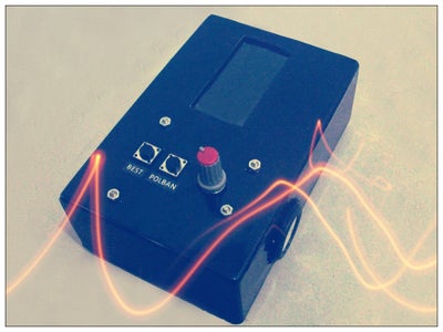
Step 9: The Enclosure


The size of enclosure are 14x9x5 cm. But you can use other enclosure that will fit to your circuit.
Step 1
see the pattern on image 2,
- we will have a rectangular cut for LED display, about 6x3 cm
- small circular cut for potensiometer,
- 2 small square cut for 2 push buttons,
- and about 0,5 mm (diameter) hole for placing a spacer (the spacer is for support the Arduino) (see yellow dot on image 2)
Step 2
On the left side of the box, there will be 2 square cut for jack power of Arduino. And make another 0,5 mm (diameter) for placing 3 spacer of Theremin PCB. We will put three spacer by 0,5 cm high. (see image 3)
Step 3
On the right side of the box, make a big circular cut for a speaker. (adjust with the size of your own speaker) (see image 4)
Step 4
And make another 0,5 mm (diameter) for placing 5 spacer of LED PCB by 0,5 cm high. (see image 5)
we're gonna attach the LED PCB with nut to spacer (marked by a,b,c) and leave the X spacer just for support the PCB.
Step 10: Put the Circuit Into Enclosure


Step 1
Put the push button circuit into the enclosure, drop some hot glue to it. (see image 1)
Step 2
Add potensio beside the push button circuit. I'm using a duct tape to avoid the potensio have a contact with Arduino (see image 1)
Step 3
Add the spacer (2 cm high) to support the Arduino inside the enclosure. (see image 1)
Step 4
Put the Theremin circuit into enclosure. (see image 2)
Step 5
For the front display, I cover it with a plastic coating that's thick enough, and cover it again with layer that slightly darker. (see image 3)
Step 6
Put the Arduino and the speaker into enclosure. Put LDR in a position where it will receive enough light from the LED Display. (see image 4)
Step 7
Put LED display on the back side of the enclosure. (see image 5)
Step 8
*Arduino
- Pin 2 = red wire, from push button 1
- Pin 3 = red wire, from push button 2
- Pin 4 = LED row 1
- Pin 5 = LED row 2
- Pin 6 = LED row 3
- Pin 7 = LED row 4
- Pin 8 = LED row 5
- Pin 9 = LED row 6
- Pin 10 = LED row 7
- Pin 11 = Positive lead of Speaker
- GND = Negative lead of Speaker
- Pin A0 = LDR wire, from Theremin PCB (orange-yellow cables on the picture)
- GND = connect to one lead of potensiometer 10 K (center pin)
- GND = connect to ground on Theremin PCB
- 5V = connect to positive lead on Theremin PCB
* Potensio
- The other lead (Left pin) of potensio connect to ground of LED PCB (the green one)
- Use the potentiometer to control the brightness of your sequence.
Step 11: Have Fun!!


This toy is pretty good as a present for someone special, you can give the message through the display of LEDs.
And don't forget to give me a feed back or advice because I'm just a beginner.
Have fun!
Greetings from Indonesia :)