

Introduction: Arduino USB MIDI Interface


A few weeks ago I started working on a MIDI controller using Arduino and ATmega32. I did not completed projected yet. It is under development.
You can read the whole story here http://openhardware.ro/arduino-usb-midi-controller/.
But during experiments I realized that interface module can be a stand-alone project and can be used by those who are already working on similar projects.
The project was designed to use easy to find components.
Step 1: Components

- Atmega8 microcontroller
- Socket DIP28
- USB-B connector
- Polarised capacitor 10uF ~ 50uF
- Connector 5x2 pins (optional)
- Connector 1x4 pins
- Quartz 16Mhz
- Ceramic capacitors 33pF
- Resistor 2k2
- Resistors 68 ohm
- Zenner Diodes 3V6
- Proto board
Step 2: Schematic

Circuit diagram is simple.
It is a standard schematic used for implementing USBasp programmer.
The difference is in the firmware that we will put in ATmega8.
Attachments

Step 3: Installing the USB Connector


To mount the USB connector we need to make two holes of 2-2.5mm.
Step 4: Mounting Resistors

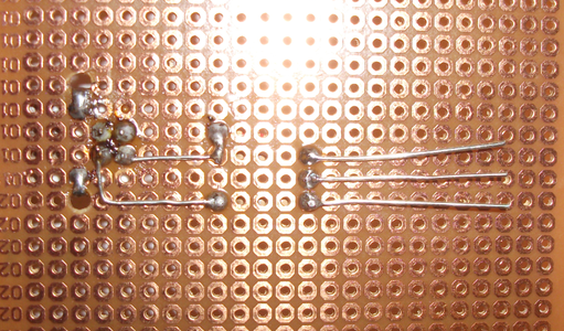
Step 5: Mounting Zener Diodes

Step 6: Mounting DIP28 Soket


... and capacitors and 16 MHz Quartz.
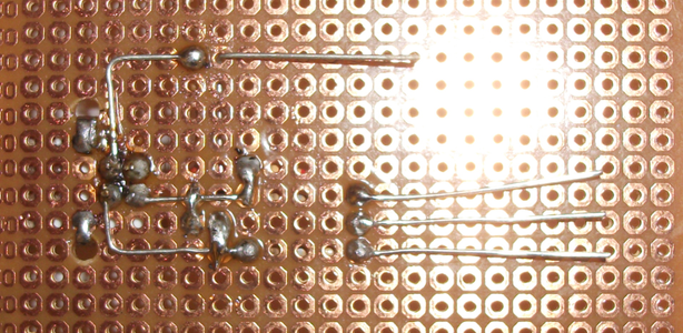
Step 7: Module Completed


Module is finished after installing 4pins connector.
From left to right:
- Pin 1 - Gnd
- Pin 2 - Vdd
- Pin 3 - Rx
- Pin 4 - Tx
I have not mounted connector 5x2pin ISP because I already had the possibility to write the firmware on a module made previously.
If you can't write the firmware outside the project will have to mount the ISP connector(5x2pin) and make connections according to schematic.
Step 8: Burning Firmware
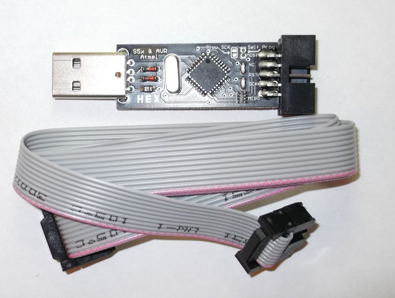
To write the firmware for ATmega8 we need a programmer. The one in the image is a USBasp. Of course you can use any other compatible programmer.
MidiShield1Hex.zip contains only hex file.
MidiShield1.zip contains entire AVR Studio 4 project.
The firmware is a slightly modified version of MOCO/MICO – USB to MIDI Converter.
.

Step 9: Using With Arduino
Now we can make connections between the Arduino board and USB module..
In fact it is simple. Just plug the serial ports of the two microcontrollers and GND:
- RX from Atmega8 to TX of Atmega32 (or TX of Arduino)
- TX from Atmega8 to RX of Atmega32 (or RX of Arduino)
- GND from Atmega8 to GND of Atmega32(Arduino)
In my set-up I am not connected VCC because USB interface is powered by USB port(or HUB) and Arduino(Atmega32) is powered separately.
Now we can make first test with the Arduino IDE. As you can see it works with the standard example File>>Examples>>Communication>>MIDI.
void setup() {
  //  Set MIDI baud rate:
  Serial.begin(31250);
}
void loop() {
  // play notes from F#-0 (0x1E) to F#-5 (0x5A):
  for (int note = 0x1E; note < 0x5A; note ++) {
    //Note on channel 1 (0x90), some note value (note), middle velocity (0x45):
    noteOn(0x90, note, 0x45);
    delay(100);
    //Note on channel 1 (0x90), some note value (note), silent velocity (0x00):
    noteOn(0x90, note, 0x00);
    delay(100);
  }
}
//  plays a MIDI note.  Doesn't check to see that
//  cmd is greater than 127, or that data values are  less than 127:
void noteOn(int cmd, int pitch, int velocity) {
  Serial.write(cmd);
  Serial.write(pitch);
  Serial.write(velocity);
}
You can also install this library: https://github.com/FortySevenEffects/arduino_midi_library. It is very helpful for making a MIDI controller with Arduino.
Attachments
Step 10: Screenshots


After I burned the firmware in ATmega8 and made connections, I connected the USB cable to the computer.
Windows immediately detected the device and installed the standard drivers. No other drivers is required (tested on Windows7-64bit and WindowsXP-32bit).
I also did tests with Fl Studio and Traktor.

Participated in the
Tech Contest


