

Introduction: Arduino USB


LOG: Made a correction/modification Step 3 and added a picture step 5.
So many Arduino users have RBBBs(Really Bare Bones Board (Arduino)) or Anarduinos or Boarduinos that could use a USB interface to program and power them but don’t want to spend $15-20 for a USB BUB or FTDI cable. This Lazy Old Geek is one of them.
Theory: Most Arduino clones are programmed with a PC using a USB port. Theoretically, they could be programmed with an RS232 port but it is really hard to find a PC with RS232. Some Arduino clones come with a USB converter but most do not. Most require a TTL serial connection. TTL stands for Transistor-transistor-logic which basically means 0-5Vdc logic. So these Arduinos require a USB to TTL converter. One of the more common is the USB-BUB by Modern Devices:
http://shop.moderndevice.com/products/usb-bub
I own one and like it but they’re costly.
So I saw these (see picture) USB to RS232 Serial DB9 Adapter cables on ebay for less than $2 so I bought one. Since I had three weeks to wait for it, I thought about and realized that it probably wouldn’t work as true RS232 has plus and minus 3-15 Vdc signals. The Arduino requires TTL levels which are 0 and 5 Vdc. Nevertheless, I’d already bought it so I took it apart. It apparently had a PL2303 chip in it and I saw no level converters. Anyway, I don’t have any kind of RS232 device to check it with but don’t see how it could ever work with a true RS232. But the other thing is; I couldn’t get it to work with an Arduino. If anyone has gotten one of these to work, please let me know how.
Next I saw this article about converting a camera adapter to work with an Arduino.
http://www.uchobby.com/index.php/2009/10/04/diy-usb-to-serial-cable-for-3/
You might be able to get these adapters cheaper than the one I used. Following the guidelines it should work fine.Step 1: My Arduino USB
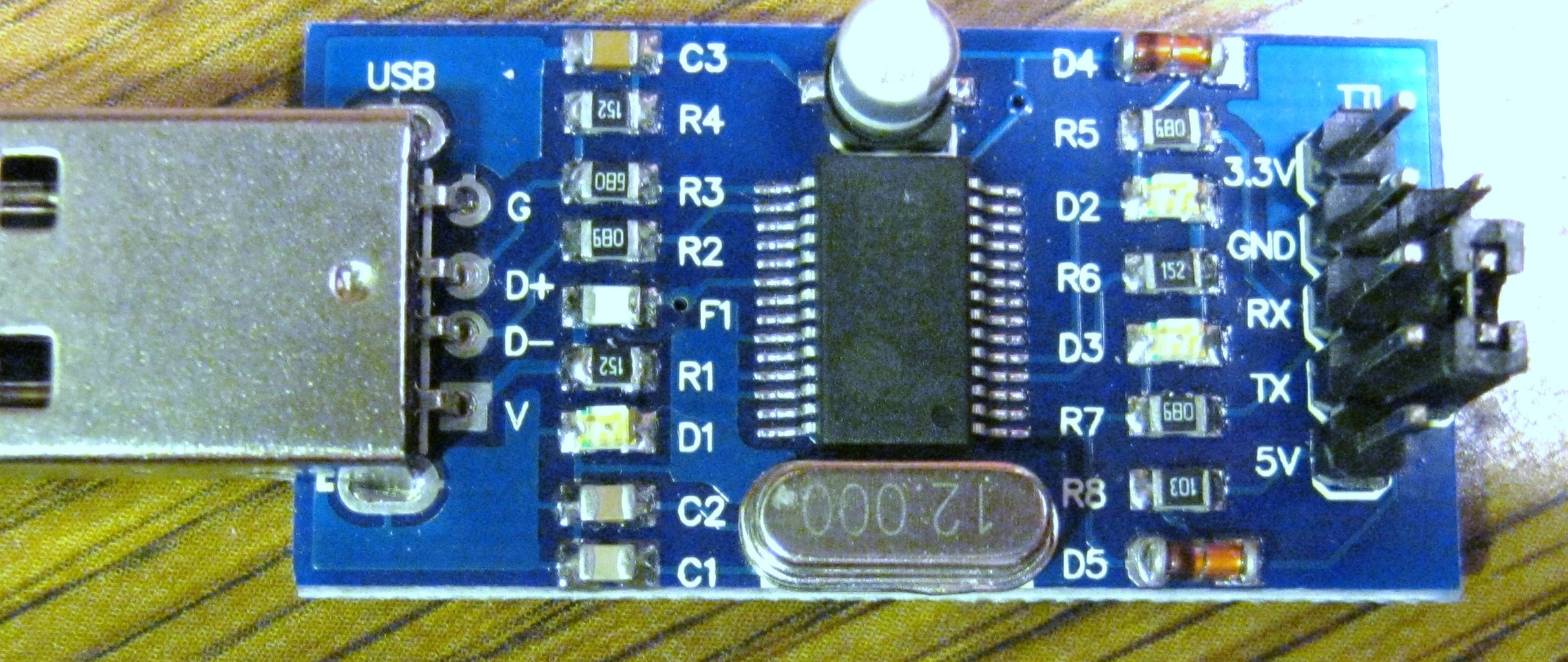


I bought this PL2303 adapter on ebay.com.
USB2.0 to RS232 TTL Converter Module PL2303 +4pcs cable
But they can also be bought directly from Virtual Village
for $2.99 plus $0.99 postage and handling. I’ve had good luck with Virtual Village.
Likes:
Well made board, works with TTL.
Fused
LEDs for power, TX and Rx
Dislikes:
No schematic, operating instructions
Uses a standard USB connector instead of a mini.
Other parts needed:
2- 6 pin female headers
Wire
Optional parts for auto reset:
1 capacitor 0.1uFd (104)
1 male header pin
Wire wrap wire or magnetic wire.
Total cost should be less than $5.
Step 2: Functional Test
So let’s see if the adapter works. If you look at the picture, you’ll see a two pin jumper on the outer, lower two pins. There is no documentation but this appears to be a loopback jumper. It connects TX to RX so anything sent out is fed right back in so leave it on for now.
Plug it into a USB port on your computer. You should here a kerchunk on your speaker and the red LED on the adapter should light up. Now my Microsoft Vista machines automatically found the PL2303HX drivers but if you need to find them, they are here:
http://www.prolific.com.tw/eng/downloads.asp?ID=31
Prolific is the company that makes the PL2303HX used by this adapter. (TW stands for Taiwan). Find the driver for your operating system and install it.
I am assuming that you have Arduino software installed. Open it up. Click on <Tools><Serial Port> and select the correct COM number for the PL2303HX.
If you have several Com ports listed and don’t know which one then you need to go into Device Manager. For my PC with MS Vista, I do the following:
Click on the little Start icon, lower left corner
Right click on the <Computer> icon
Select <Properties>
Click on <Device Manager>
Click on <Continue>
Next to the <Ports (COM&LPT)> icon, click on the <+>
The drop down should show <Prolific USB-to-Serial Comm Port (Com4)
Or something similar. The Com port is the number.
Go back to the Arduino software and select the correct Com port number.
On the Arduino screen select the far right icon <Serial Monitor> or press <Ctrl><Shift><m> at the same time.
A serial monitor window should open up. Type something into the text box. Hit <Enter>. The typed text should jump down into the second text box. That means the text is going out the TX pin, into the jumper and back into the RX pin.
The adapter is working correctly. Remove the jumper.
Step 3: Decision Time: Auto Reset or Not


When you send a sketch to the Arduino, it will briefly pull a serial pin called DTR low which will reset the Arduino. This can be done manually by pressing the Arduino reset button for a few seconds after sending the sketch. Timing this correctly is a little tricky but can be done successfully with some practice.
Now this adapter doesn’t use the DTR pin, so it has to be modified to be able to use it. This requires some good soldering skills that you have to decide if you have. I was able to do it and I’m old. But it wasn’t easy. If you want to skip the Auto Reset and do the Reset manually, skip the rest of this step.
Okay you have to solder a wire to one (and only one) pin on the PL2303 chip. The pins are 0.025 inches (0.65mm) apart. That’s not very much. A wire needs to be attached to pin 2 (DTR_N). But it can easily be shorted to pin 1 or 3 so be careful. Here’s what I did.
My soldering iron had a plain copper tip. I sharpened it to a point. I put a cutoff wheel in my drill press to do this. By the way, I did the same thing to my DMM probes. You can also do it with a file. Plug in the soldering iron and tin the tip.
The wire I used is 30AWG wire wrap wire. I know others have used magnetic wire but I don’t have any or know where to get it cheaply. I happened to have some wire wrap wire but it can be purchased at Radio Shack or ebay.
Slightly irrelevant information:The little tool I have is a great way for stripping off insulation of wire wrap wire. You just slip it into the notch in the middle of the tool, pull it down into the V and pull the wire out. Unfortunately, I priced these tools new and they’re about $25-$30. Outrageous.
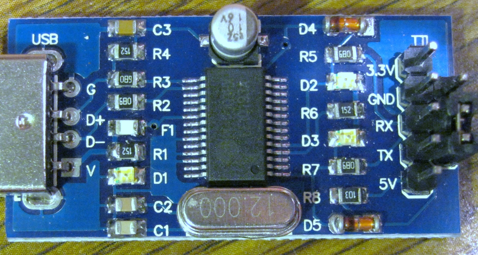
Okay, so using reading glasses, a magnifying glass and a bright lamp and a little solder, I was able to get it soldered. See picture. Note the little circle on the PL2303Hx chip that indicates pin 1 and that the wire is soldered to pin 2.
If you have a DMM with sharpened probes, make sure that the wire is electrically connected to pin 2 and not to pin 1 or pin 3.
Next, I hot glued the wire to the adapter PCB. It actually covered up D3 the LED for TXD but it’s clear and the light shines through it. See picture.
I hot glued a 0.1uFd capacitor (104) to the top of the PL2303HX chip and soldered the other end of the wire to one side of the cap.
The other end of the cap goes to the Arduino reset pin but I decided to put it on a header pin so that I can make jumper cables for it.
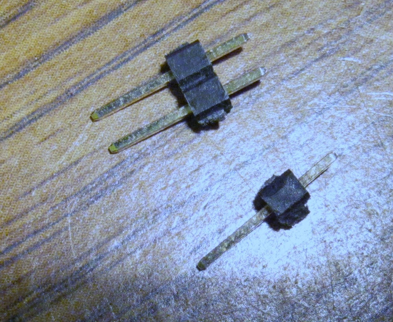
I snipped off a single male header pin and soldered some wire wrap wire to the short side and clipped it short as much as I could. See picture.
Then I stuck the single pin into a female header. See picture. Actually, I have some 50 pin headers but only needed six pins. To trim this, what I do is go to the pin past the ones you need (in this case the seventh). Take a utility knife or Xacto and scored in the middle of where the pin runs. Do both sides a couple of times. Then carefully bend the header until it breaks apart. You will have an extra metal contact to toss or recycle.
On the adapter, there is a five pin strip of male pins labeled TTL. I put the female header on the strip so that the extra pin was just past the pin labeled 3.3V.
Caution: Though the PCB is coated, the clipped off solder connection can be sharp and penetrate the coating. This happened to me on another of these so I had to stick a piece of tape under it to insulate it.
Now the insulation on this pin sticks up a little higher than the other five pins because of the wire and solder. But this is okay. The PCB is coated. Then I hot glued the DTR pin to the PCB.
Then I soldered the other end of the wire wrap wire to the capacitor. See second drawing.
Step 4: Wiring It Up


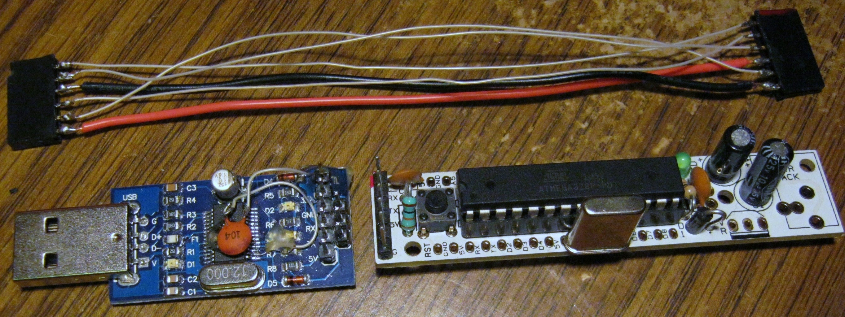


Many Arduinos like the Anarduino, RBBB and Boarduino have a USB connector with six pins configured as Gnd, Gnd, 5V, Tx, Rx, DTR. So I decided to make a six pin female to six pin female adapter cable to go between my adapter and my Arduinos.
TIP: I have a USB BUB and use it on Anarduinos and RBBBs. They look quite differently and it is easy to put the USB BUB on opposite from what it should be. I have done this several times. I’ve been lucky that I haven’t had any apparent damage. To help prevent this I borrowed some nail polish and painted the DTR side red on both the USB BUB and the Arduinos. Now I just have to match the reds so that I don't put it on reversed. See picture.
Notice that for the six pin female header in the picture, I cut a little notch out of one pin. This is so it will fit better on the DTR pin which is sticking up a little bit. This will also identify which of the headers goes onto the adapter since they’re both six pin. I also plan to borrow a different color nail polish for this DTR pin. (see picture)
Rules:
NC means no connection
Like pins connect to each other, e.g. Tx to Tx
My adapter header has the notch for the DTR pin .
Decisions: If you decided not to use DTR then you connect the following:
Adapter Arduino
NC NC
NC Rx
Gnd Tx
Rx 5V
Tx NC
5V Gnd
Just four wires. If you don’t need 5V from USB to power the Arduino, then skip the 5V also.
If you have DTR wired up then connect the following:
Adapter Arduino
DTR DTR
NC Rx
Gnd Tx
Rx 5V
Tx NC
5V Gnd
*********WARNING*********************************
The Anarduino has a ground connected to two pins of the serial male header strip. Apparently, so does the Boarduino. If you are using one of these, then the following cable won’t work and can easily damage the USB adapter chip. I modified my Anarduinos so that this will work. The RBBBs are okay.
*********WARNING*********************************
Now, my cable will be a little different as I have RBBBs and I modified all of my Anarduinos so that they can accept 3.3V on the second ‘Ground’ pin. This is a jumper option of the USB BUB. Since most of my sketches use 3.3V to set Aref, I will wire it up in my cable.
Caution: If you do use this 3.3V be careful as it isn’t clear (to me anyway) how much current the chip can supply. The PL2303HX has a 5V to 3.3V converter in it, but this 3.3V is also the main power supply for the rest of the PL2303HX. In my designs, I use 3.3 for Aref. It is drawing less than 0.1 mA so shouldn’t be a problem.
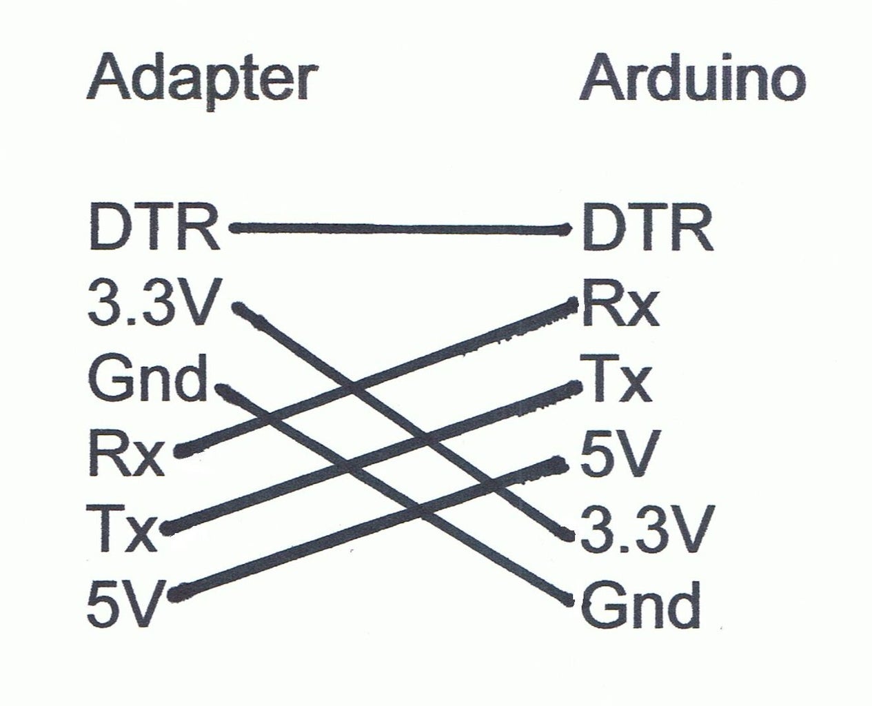
Adapter Arduino
DTR DTR
3.3V Rx
Gnd Tx
Rx 5V
Tx 3.3V
5V Gnd
For this cable, I made the wires 5” long. Note that I used heavy wire for the Ground and 5V and used wire wrap wire for the other signals. The 5V and Ground will need to carry a little more current. Plus this adds a little strength to the cable. I wrapped some electrical tape on both headers as additional strain relief.
My adapter works great!
One of the advantages of using a cable is that you can make several different ones. You might want a short one or in my case, I might want one without the 3.3V. If you make several, you might want to label them.
Step 5: More Info and Conclusions
Level Translation:
If you read the article about the other adapter I referenced, he talked about Level Translation. He is basically correct. The signals coming out of this adapter are 3.3V and will work with Arduinos.
For the one signal, Rx coming from the Arduino, I ‘reverse engineered’ the adapter circuitry. They have a resistor and diode in the circuit that will limit it to 4V. Plus the PL2303HX documentation does say that it is 5V tolerant. Plus on the adapter, the five pin connector says "TTL' which means 0-5V. For all of these reasons, I didn’t feel the need for a voltage divider.
For all of you electronic circuitry geeks: If you look at the schematic for the Anarduino, Boarduino and RBBB, the DTR (sometimes identified as RTS pin) going to the USB connector has a 0.1uFd capacitor before it’s connected to the Reset pin on the AtMega. And further perusal of the USB-BUB schematic and my adapter shows another 0.1uFd capacitor from the DTR pin of the converter IC to the connector. So there are actually two 0.1uFd capacitors in series.
So what does that mean? Well, many of you know that if you connect two resistors in series, the resistances add. Two capacitors in series are different. The actual formula to find the capacitance is C1*C2/(C1+C2). So the equivalent capacitance is 0.05uFd.
So other geeks may be wondering what is a capacitor doing in the middle of digital circuitry? Here is basically what happens. When the USB is ready to operate, it sets DTR low. This low signal is passed through the capacitors and pulls the Reset* pin on the AtMega low for a short period of time. This resets the AtMega. The capacitors will start to charge up so the AtMega side will go back to 5V and the AtMega will resume operation.
Caution: I noticed that the PL2303 adapter that I received is slight different from the adapter in the picture from Virtual Village. I hope that mine is the current version and that they are no longer selling the other version. But if you do get one of these and it’s different you may have to wire it differently.
This adapter also comes with four piece cable. If you are not using auto reset and/or have extras, you can use these instead of making a cable like I did.
There are several other versions of PL2303 adapters. Some of them have the DTR pin connected so that you wouldn't have to do the modification I did. However, the one I saw was a lot more expensive.
Conclusion: Well, I hope this helps some of you save some money.
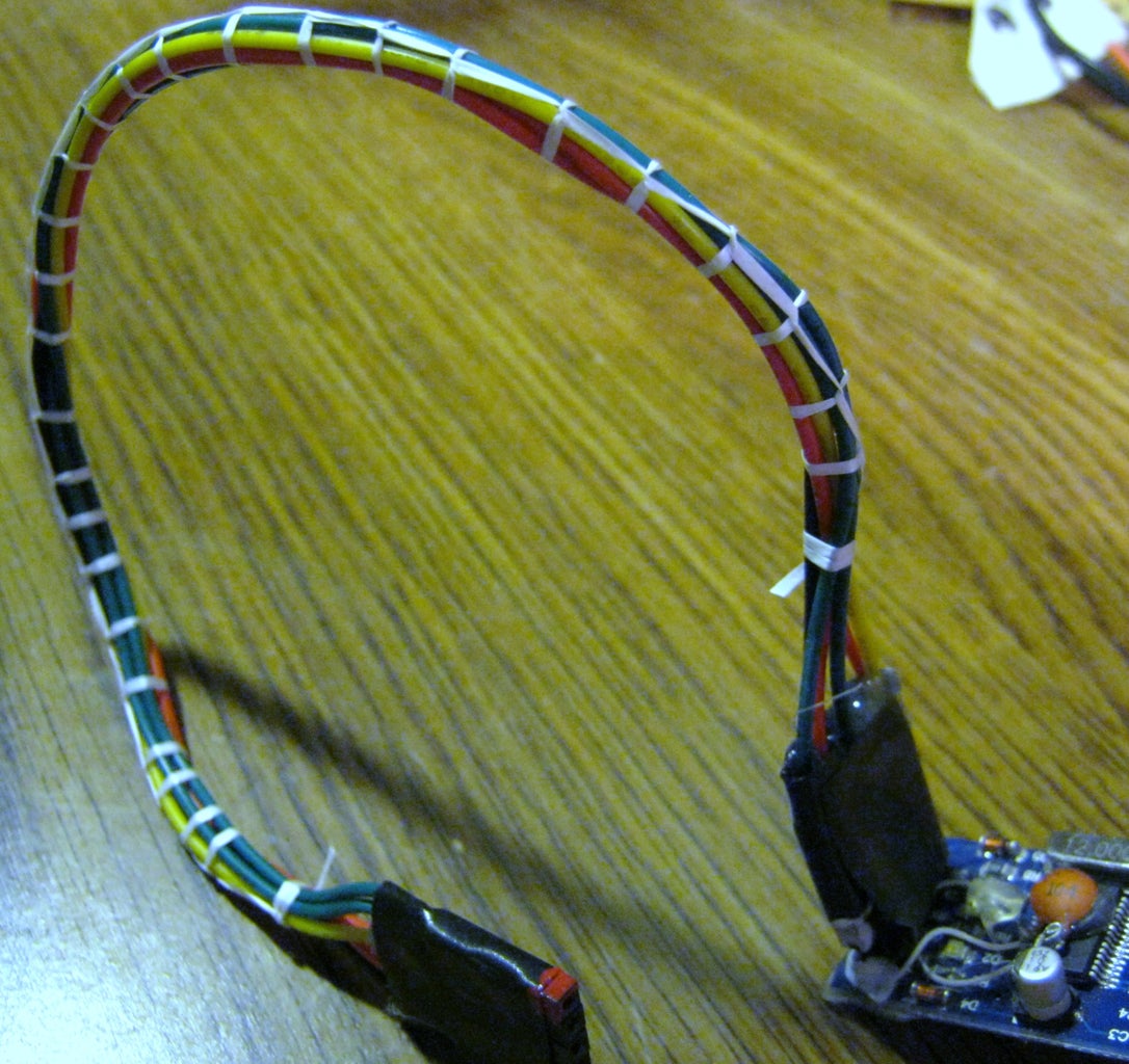
The last picture is an adapter cable I finished with something called cable lacing.
This was done with some waxed dental floss that I got as a sample from my dentist. I don't really have the a very good technique so won't go into details but if your interested, just do a search on 'cable lacing.'


