

Introduction: Arduino Ultrasonic "Parking Spotter"


For my first instructable, I'd like to present The Parking Spotter. This is not a new concept, I know. However, this build was done specifically to suit my needs/wants/materials already in my possession. Typically, a project begins with an idea, parts are then gathered, and the building commences. In my case I looked around at the parts and material that I had on-hand, browsed Instructables (a daily occurrence), and found inspiration from others. I shouldn't fail to mention the site of wooden saw horses in front of my sister-in-laws $30k car to protect the $200 bicycle!! So, let's dive in!
BOM (bill of materials):
* Arduino Uno, clone (Freeduino, etc.), compatible (Perfboard Arduino, etc.)
* SRF04 Ultrasonic Ranging Sensor
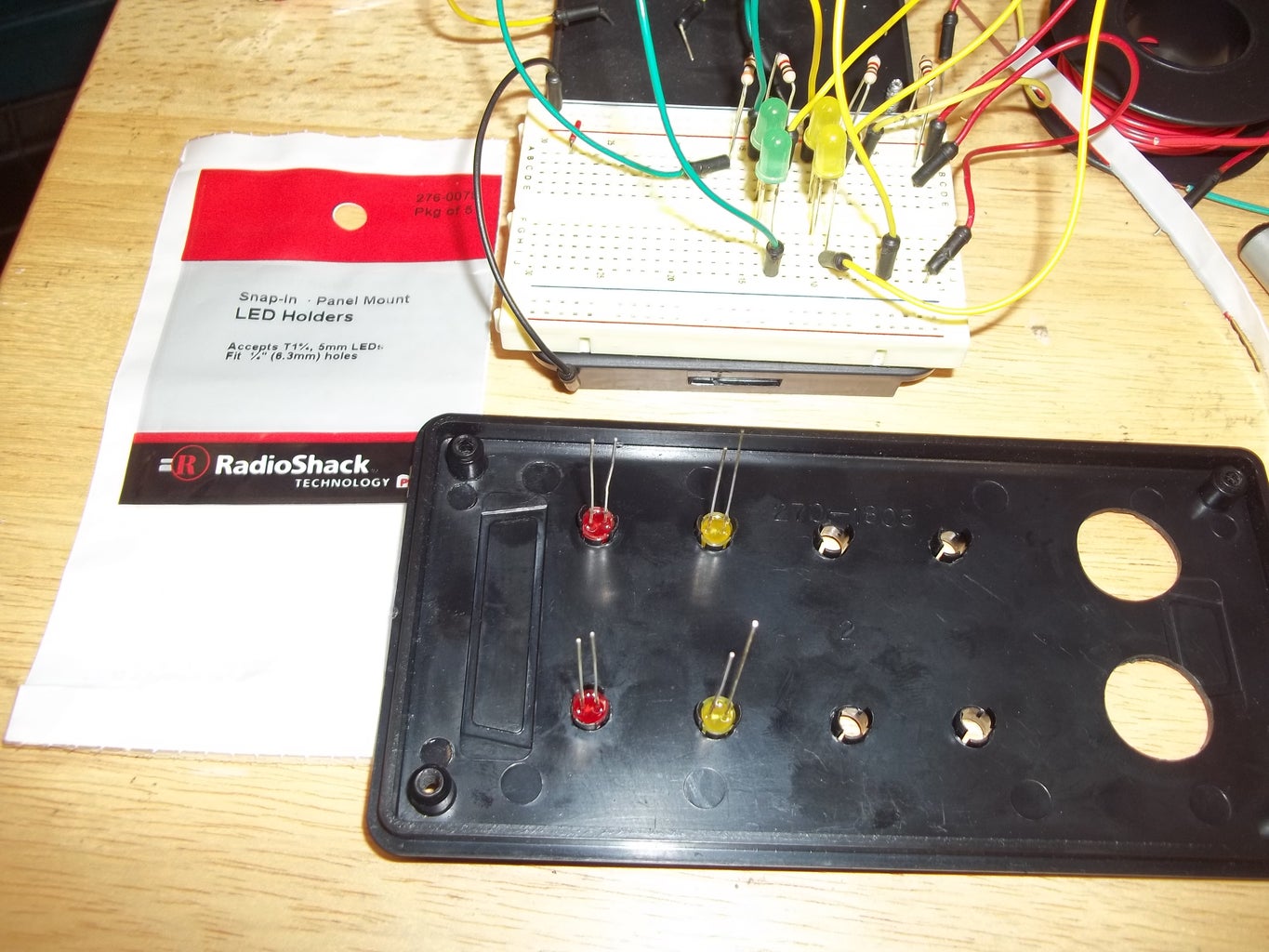
* (8) 5mm LED's for indicator lights (I used red, yellow, and green for this project; but you can use whatever colors you would like)
* (4) Appropriate resistors for your LED's (I used 100 Ohm for red & yellow, and 82 Ohm for green)
* (9) LED holders of your choosing (I used LED Holder Model:276-079 for the indicator lights, and LED Holder Model:276-080 for the power indicator/pathway light)
* (1)Power-On/Walkway 5mm LED & resistor(for pathway illumination in front of your car)
* SPST switch (power)
* Power source - I used a wall wart with 7.4v DC output because, well, I had one on my bench. You can use a 9v battery & battery clip. I just don't want to mess with batteries.
* Wire
* Heat-shrink tubing and/or electrical tape
* An enclosure (I used the plastic 4" x 6" enclosure from Radio Shack)
** Optional:
* One row of (5) male header pins
*Hook-up wire with female connectors: (5) for the LED's & (4) for the sensor
* PCB standoffs
* cyanoacrylate (super glue, finger nail glue)
Tools:
Soldering iron, solder & fume extractor
Drill or drill-press
Appropriate drill bit for your LED holders
5/8" drill bit for the sensor holes
Screwdriver for the enclosure
Third-hand
And, anything that you feel you need to make your task easier.
I am going to assume that you are, at least, familiar with the Arduino development platform. If you are not, I suggest visiting the Arduino homepage. Study the hardware and software. Learn the basics. Build some circuits (actually, this could be your first! It's not that hard!) When you have reached that point, learn more! I've been learning this stuff on my own with TONS of help from the wealth of information on the Arduino site, great Instructables members and the web in general.
Attachments

Step 1: Layout Design


As I said, the choice is up to you as to what Arduino or Arduino-compatible board you use. As for me? Well, I built my own board based on this Instructable - Perfboard Hackduino (Arduino-compatible circuit) by jmsaavedra and the paper breadboard overlay from Sparkfun. Pay close attention to the 5v regulator part of the circuit in the Perfboard Hackduino 'able, though. Read the entire 'able & comments before you start. It's good, but can be confusing if you don't pay attention.
Referring to the photo 1 notes, there are two sets of red/black wires. The set toward the top of the picture is for a power indicator LED & the other is for power. I used a wall wart with an output of 7.4v DC. You can use a 9v DC battery, if you prefer, but I didn't want to have to mess with changing batteries.
Once my perfboard had the ATMega circuit on it, I prepared my enclosure. I laid out the parts (8 LED's with resistors & ultrasonic sensor) on the lid of the enclosure to determine two things: aesthetics & roughly how much wire I would need (Sorry, no pics of this step). The placement can be of your own liking. I got my inspiration from yet another Instructable, Ultrasonic Parking Sensor by atatistcheff. I like a lot of LED's. :)
Step 2: Construction Begins


Once the locations were determined, I marked & drilled the holes for the (8) LED's & the sensor.
As you can see in the first photo, I was going to use the metal cover that came with the enclosure, but later scrapped it.
In the second photo, you can see that my 5/8" holes may have been a "bit" big. But, I discovered that a standard garden-hose rubber washer fits over the sensor "barrels" perfectly. So, I glued them on with cyanoacrylate (super glue, finger nail glue) and then colored them with a black permanent marker. Problem solved! :) This also holds the sensor nearly flush with the enclosure.
You also need to prepare the enclosure for mounting your circuit board, switch, power indicator LED &, if using a wall wart, a place for the power to enter. If you're using the same enclosure as me, it is deep enough that you can mount the board anywhere on the bottom and have plenty of clearance. Mark the holes and drill them. You can test fit the board but, if you're using a board without female headers, you will need to take it back out for soldering.
The power/illumination LED gets mounted so that it will be shining on the ground, & the switch can be wherever you would like it. Drill the appropriate size holes for your components.
One last hole. It's for the wall wart wire. I placed mine at the back of the bottom of the enclosure.
Clean all holes of any burs left from drilling.
Now is the time to make sure you know which pins are what on the SR04 ultrasonic sensor. I have marked the voltage pin red & the ground pin black with permanent marker & wrote the pin description on the back of my overlay paper. See photo 4.
Next, mount the LED's using the LED holders or glue, and the ultrasonic sensor with glue.
Step 3: Let the Soldering Begin!


Time to start soldering.
Working on the inside of the lid: The LEDs are soldered: red-red in series; yellow-yellow in series; yellow-yellow in series; green-green in series, along with the (4) resistors as mentioned in the BOM: (100 Ohm for red & yellow, and 82 Ohm for green). I forgot about the heat shrink until I had the LEDs connected so, I wrapped a piece of electrical tape around them & placed heat shrink on the common cathode. I then soldered all of these leads to the 5-pin-row male header. NOTE: By using the center pin for ground (-), if you plug it in backwards, it will still work. A good bead of hot glue was then applied to secure the header to the lid. (Photo 1)
For the connection wires, I used female jumper wires with one end cut & stripped. Make things easy on yourself -
LED distance indicators wires: red wire for red LEDs, yellow wire for yellow LEDs, green wire for green LEDs.
Red wire to Digital Pin 5 (chip pin 11)
Yellow wire to Digital Pin 4 (chip pin 6)
Yellow wire to Digital Pin 3 (chip pin 5)
Green wire to digital pin 2 (chip pin 4)
Another dab of hot glue to help secure the wires onto the board.
Ultrasonic sensor wires: red wire for VCC (+), green wire for trigger, orange wire for echo, black wire for gnd (-)
Red wire to +5v on board
Green wire to Digital Pin 8 (chip pin 14)
Orange wire to Digital Pin 7 (chip pin 13)
Black wire to ground (-) on board
Now take your female wire ends and super glue them together in their respective groups to form plugs; LED wires in one plug & sensors wires in the other. You could omit the two plugs and just solder the wires directly to your components, but it's nice to be able to completely separate the lid from the base when working on things.
Step 4: No Need to Feel Powerless!!!


I cut the the plug off the wall wart, leaving it as long as possible, and stripped the ends of the wire, ran it through the hole drilled for it and soldered it according to the picture-notes in photo one:
#1: (+) from power supply (wall wart) to switch.
#2: (+) from switch to regulator circuit on board.
#3: (-) from wall wart to (-) of regulator circuit on board.
Next is the Power indicator LED:
#A: Knot tied in wire from wall wart AFTER feeding it through the hole, BEFORE soldering them!
#4: (+) & (-) from voltage regulator circuit to power indicator LED.
#4a: (-) for LED.
#4b: (+) for power indicator to 100 Ohm resistor to LED anode.
#5: Pathway Illumination LED mounted to bottom (when mounted on wall) of enclosure.
I love hot glue! It helps hold wires in place nicely!! :)
Step 5: And One Sketch to Rule Them All


I included the MsTimer2.h & NewPing.h files for better accuracy.
For the other changes, you can compare the three sketches. I'll not try explain them, because I'm not a programmer. Besides, figuring out some of this stuff on your own is part of the fun. Not to mention the fact that Michael LeBlanc did most of the changes, and did them well. Thank you, Michael!
The biggest change I made was:
From this:
The circuit:
* +V connection of the PING))) attached to +5V
* GND connection of the PING))) attached to ground
* SIG connection of the PING))) attached to digital pin 7
The PING))) is a three-pin sensor: the trigger & echo are on the same pin.
To this:
The circuit:
* +V connection of the SRF04 attached to +5V
* GND connection of the SRF04 attached to ground
* Trig "Trigger" connection of the SRF04 attached to Digital pin 8
* Echo connection of the SRF04 attached to Digital pin 7
The SRF04 has separate pins for trigger & echo.
So, this:
const int pingPin = 7;
Became:
#define TRIGGER_PIN 8 // Arduino pin tied to Trig pin on ultrasonic sensor.
#define ECHO_PIN 7 // Arduino pin tied to Echo pin on ultrasonic sensor.
I don't remember why I changed const to #define, but it works. :)
Now, before you install it (hang it on the garage wall), find someone to help you calibrate it. To do this, I held the device against the wall & my brother drove the car, stopping at each stage of lighting. Measurements were taken, & it was agreed that I nailed it the first time. No need for adjustments! This is because I had measured before I uploaded the final sketch, and input my numbers into the code. Something I could have mentioned sooner.
Distances can be changed to suit your needs. Look over the sketch and see what you've learned or can learn. If you have specific questions, ask. If I can't answer them, maybe someone else can.
Thanks for checking out my first Instructable! I hope it was interesting enough for you to be reading this sentence!! :)
P.S. - Check out The Parking Spotter on Adafruit's Show & Tell from 1-5-2013 (my segment starts at 17:40) & on the Adafruit Blog
Attachments

Participated in the
Holiday Gifts Contest

Participated in the
UP! Contest

Participated in the
Instructables Design Competition


