

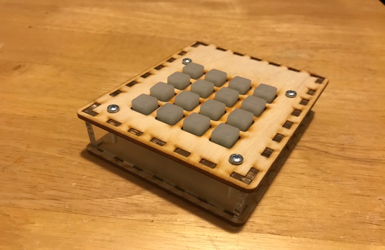
Introduction: Arduino Uno Midi Controller


This project is loosely based on adafruit's UNstrument. I read a few articles/instructables and they have outlines for designing DIY MIDI controllers, but all of these exampes involve an Arduino Leonardo. I only have an Arduino UNO, so many of the libraries available to the Leonardo, are not campatible with the UNO. As a result, I had to design my own MIDI controller using an Arduino UNO.
My MIDI controller uses the trellis keypad as its main interactive interface. This touch pad detects which button is pressed by the uses this as mapping to output a speciific MIDI value. I tested my MIDI controller using a Max patch. Since we map buttons pressed to MIDI data, we can use the outputted MIDI data to map it to a chosen sound or sample.
Step 1: Parts List


1x Arduino UNO
1x Trellis Keypad
1x Rubber pad for Trellis
16x LEDs (green color for this instructable)
1x Soldering Kit
1x Laser Cutter
1x Plywood
Step 2: Assemble Trellis Keypad


Adafruit Setup Tutorial: https://learn.adafruit.com/adafruit-trellis-diy-op...
First, we will assemble the Trellis Keypad. Choose LEDs of your liking and solder them to the PCB. Make sure that the LEDs are not longer than the rubber pad! Once you have successfully soldered the LEDs into place, solder a 4 different colored 2.5" wires (for easy identifications).
Step 3: Test Trellis Keypad
Adafruit setup: https://learn.adafruit.com/adafruit-trellis-diy-o...
Connect SDA to A4, SCL to S5, 5v to 5v, and GND to GND. Test your Trellis pad using the above sketch. This sketch will turn on an LED when you pressed the selected the button. For any issues, you may need to either resolder the LED or refer to Adafruit's tutorial.
Attachments

Step 4: 3D Print Trellis Housing Pad


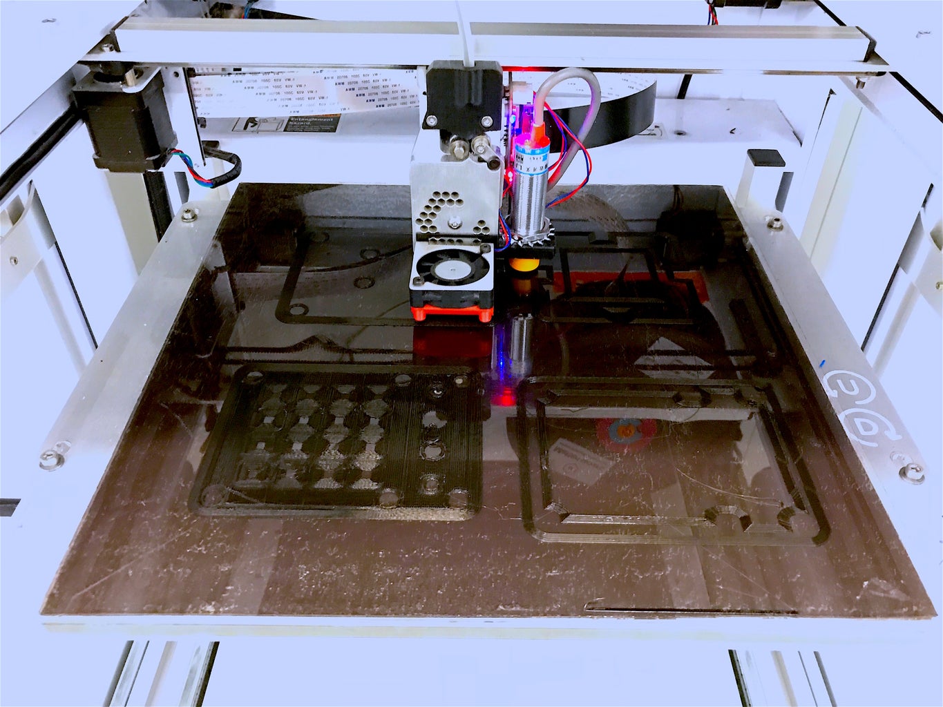
We will eventually need to secure the Trellis pad to the enclosure, so we will need to 3D print the housing pad for the Trellis. Use the above sketch and choose a preferred printing thickness. Beware that although a thicker print will be a lot more stable, it could result in a potentially too small or too tight housing pad.
Attachments

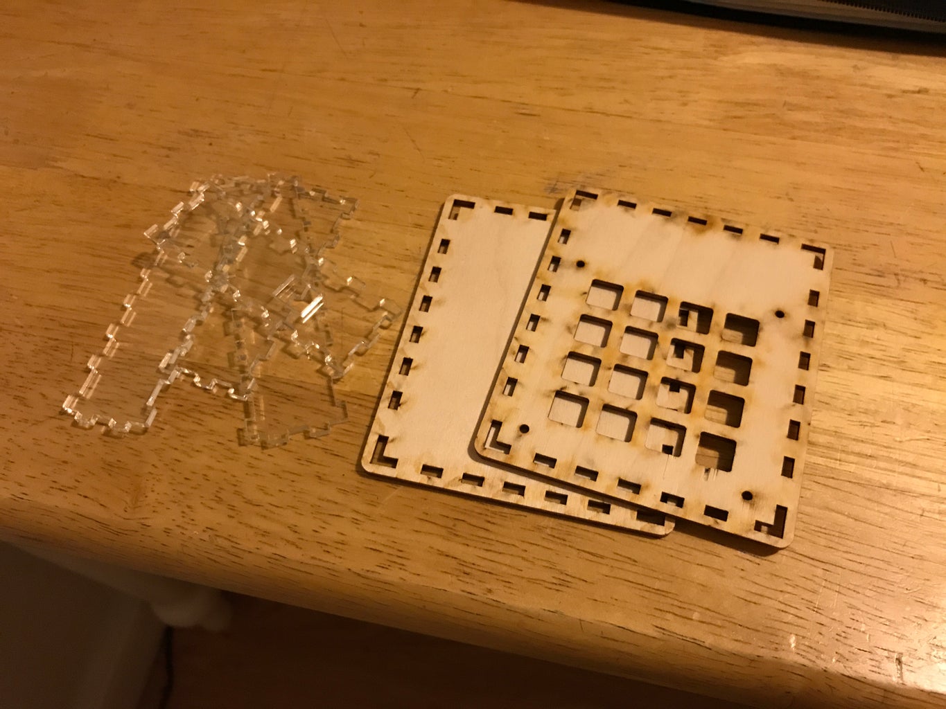
Step 5: Design Enclosure
We will use MakerCase to design the enclosure. Choose a box size that will fit the Arduino UNO and the Trellis keypad. Once you have the .svg file, open it in Illustrator and edit it so it has the correct size holes for the Trellis buttons, holes for the housing pad, and a sqaure hole for the Arduino's USB port.
Attachments
Step 6: Assemble MIDI UNO

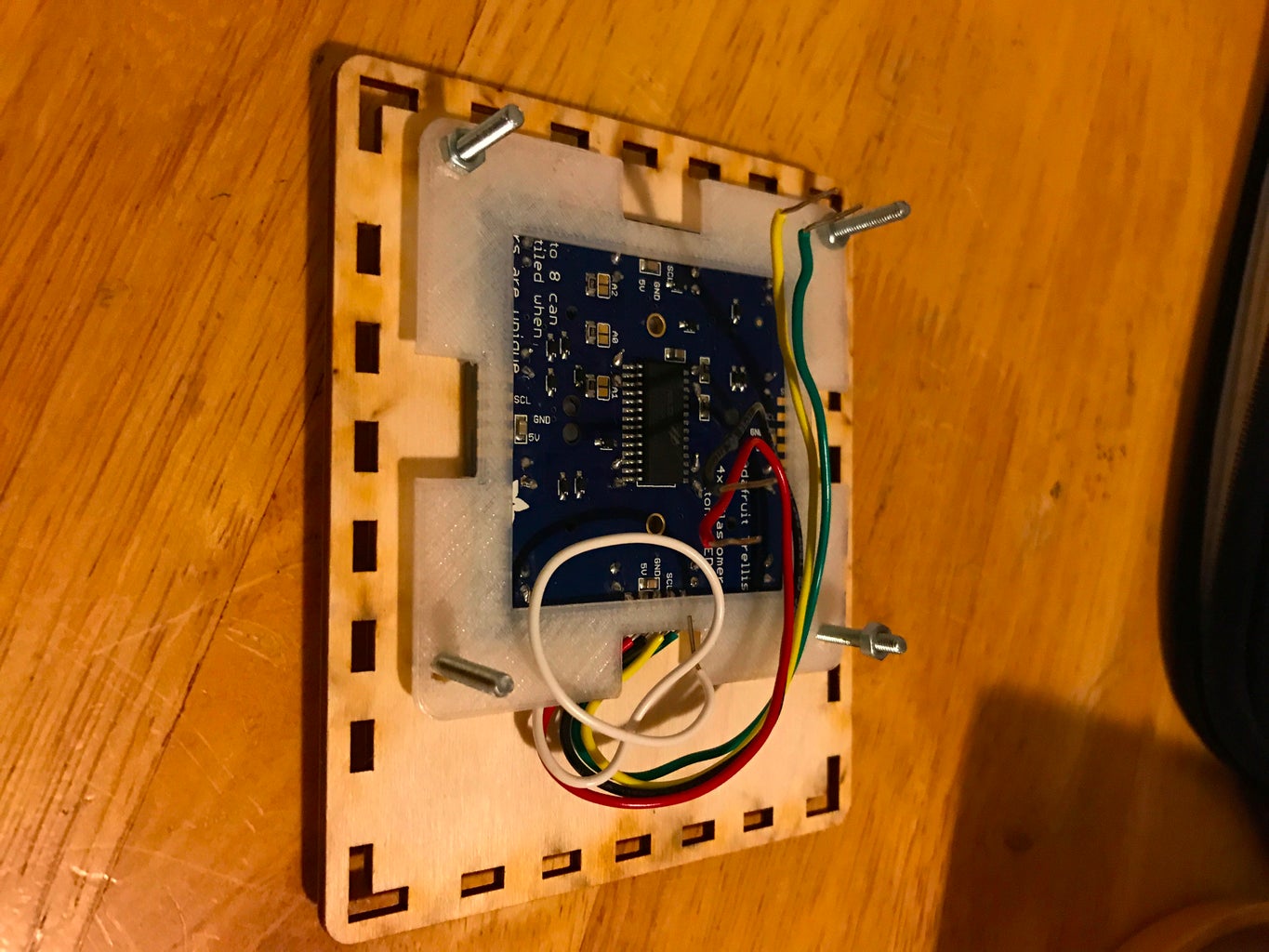

Now that we have all our enclosure parts, it is time to build your device. Assemble the base of the enclosure, by securing the sides to the bottom plate. Next, screw the housing pad with the Trellis Keypad to top plate. Make sure that you position the keys so that wires are facing the long side of the front plate. Once you are satisfied with these prior steps, attach the top plate to the base. Congratulations, you have assembled all the hardware for you Arduino UNO MIDI Controller.
Step 7: Upload MIDI Sketch

Upload this sketch and test that all your Trellis buttons work. We have modified this sketch, so that when a button is clicked, it stays on for however long the button is held and then prints a number between 0 and 255 to serial. Check that the number is correctly sent by viewing the Serial Monitor. These number represent MIDI data, which refer to a specific pitch in Music softwares.
Attachments
Step 8: Send MIDI Data Using Hairless MIDI

Hairless Midi: http://projectgus.github.io/hairless-midiserial/
Now that we can register buttons and send MIDI data through the serial port, we will use the Hairless MIDI to formally convert these serial numbers to MIDI. This program will allow your music software to register the Arduino UNO as a MIDI device.
Step 9: Create Music!
Flying Kickapow! Congratulations, you've created an Arduino UNO MIDI controller. Start making music and test how this controller works in popular music softwares, such as Abelton, Logic Pro, and GarageBand.

Participated in the
Makerspace Contest 2017


