

Introduction: Arduino Watch Build Instructions


Update: New version out that works with Arduino 1.0 and higher!
The Arduino Watch provides augmented sensing of temperature and range, 16-bit color drawing program, Breakout game, and also tells the time in your choice of digital, binary, or analog. Additional sensors, devices, and programs are easy to add as any standard Arduino.
The source code can be downloaded from the google code page, code.google.com/p/arduino-watch.
Updates and news on the Arduino Watch can be found at OptimizedForce.com
This is a video that gives an overview of what the Arduino Watch can do.
Step 1: The Materials

The materials used in making the watch are
Electronics
1 Arduino Mini Pro 328 - 3.3V/8MHz available at SparkFun
1 FTDI Basic Breakout (if you don't have one) available at SparkFun
1 4D Systems OLED Module 1.5" (128x128 pixels) available at SparkFun
1 Blackberry Trackballer Breakout available at SparkFun (I'm sensing a theme of the supplier)
1 3.7V 1000mAh Li-Polymer battery available at SparkFun
1 LiPoly Fast Charger available at SparkFun
1 DS1307 Real-time clock available at Digi-Key
1 Crystal 32kHz available at SparkFun
Nuts and Bolts available at local hardware stores
2 #4 bolts 3/8" long
2 #4 bolts 1/4" long
4 #4 bolts 3/4" long
8 #4 nuts
(for the nuts and bolts I found the brass ones at Ace and the zinc ones at Home Depot)
Watch Band
~13" x 1 5/8" leather band for the outer layer (I used a wide leather belt)
~8" x 1 7/8" elastic band for the inner layer (I used another belt)
Misc
1/4" OD copper tube available at Home Depot
1/2" thick piece of wood for screen case, I usually use poplar wood.
6 right angle header pins available at MarVac
1 Connector Housing 6 pin housing (if you can find a 5 pin housing get that) available at MarVac
2 Connector Housings 1 pin housing
7 female pins available at MarVac
1 IDE ribbon cable (dig it out of that pile of cables you never use)
Alternate parts
1 4D Systems OLED Module 0.96" (96x64 pixels) available at SparkFun will also work since I originally programmed the watch for that display until I accidentally broke mine and everyone was out of stock so I had to move to the next size up.
1 3.7V 900mAh Li-Polymer battery available at SparkFun smaller cheaper battery almost as much power.
1 Real-time clock module available at SparkFun or at RobotShop these modules would replace the real-time clock chip and the 32kHz crystal and give you a backup battery.
Attachments

Step 2: The Software

The code for the Arduino Watch can be found on my Arduino Watch google code page http://code.google.com/p/arduino-watch/.
The main file needed is the WatchRXX.pde (were XX is the current revision) and at the same location you can also download all the libraries needed for the Arduino Watch software.
Step 3: Preparing the Materials
Arduino Prep
Solder the right angle header pins to the Arduino so that you can connect the FTDI Basic Breakout board easily.
Battery Prep
Cut the JST connector off of the battery and attach the single pin housings to the ends of the wire this tutorial is useful to teach how to crimp the wires.
Step 4: Carving the Screen Case


This step covers the carving of the case for the OLED display. The frame was carved on a Carvewright woodcarving machine. Then sanded down the part and drilled the screw holes on a drill press with a 1/8" bit. To locate the holes I put the display in and marked out where to drill. Originally I tried to drill the holes in with the Carvewright but it split the frame during the hole drill and I had to start over. Next I used a dark stain to give the poplar wood a nice finish.
Step 5: Parts Layout

This step is where you layout the parts to see how long of wires you need to have for the watch. Remember that when the watch is on your wrist the parts will be closer together due to the curvature of the watch band. Tape the components to the watch band and see how it fits on your wrist and make sure everything is in a comfortable position. Layout the ribbon cable from the part to the Arduino and mark the distance on the cable (leaving wire to solder to), then cut the cable and strip the wires.
For the trackball to Arduino there needs to be a minimum of 7 wires (power, ground, button press, up, down, left, right). If you want to light up the trackball you can use more wires and connect to an available digital out.
For the display to Arduino there are 5 wires.
Step 6: Cutting the Watch Band

The step covers the cutting of the watch band to create mounting points for the trackball, display, and battery.
The screw holes are 1/8" diameter and the hole for the trackball is 1/2" diameter.
The large square in the picture was for the smaller display I was originally going to use and is not necessary. The smaller rectangle cut out is for the connection to the display which is necessary.
Step 7: Soldering Connections Diagram


This Excel file has the pin map for how to wire the Arduino to the other components.
The picture shows you what it will look like after following the next few steps.
Remember helping hands are always, well, helpful when soldering. And if your helping hands cut into your wires stick a clothes pin in the helping hand and put your wire in the clothes pin.
Attachments
Step 8: Soldering the Trackball


Place the trackball board and the trackball ribbon cable into the helping hands and solder the wires.
After soldering put a little bit of hot glue over where the wires connect to the trackball board for improved strength.
Note: To make a more compact design wires should head out to the left in the picture (opposite the direction seen below) laying flat against the back of the trackball board.
At this point it is good to test that everything is wired correctly, you can do this by uploading the the Trackball Tester software found on the Arduino Watch google code page.
Step 9: Soldering the Display Connector


Now that the trackball is connected and tested you can move to the display connector. Now you do not want to directly solder to the OLED display since it uses a serial connection to communicate with the Arduino and you want to be able to upload new sketches to the Arduino after you have completed the build (only one serial connection at a time allowed).
Use a Dremel (or other cutting tool) to cut off one of the pin slots on the Connector Housing 6 pin housing to make it a 5 pin housing. Also you can cut down the height of the housing so that it does not stick into your wrist as much.
Take the 5 wire piece of the IDE cable from the "Parts Layout" step and crimp the wires into the female pins and insert in the housing. To increase the strength of the connector (especially if you cut the height down) add a hot glue to where the wires come out of the housing.
Solder the other side of the wires to the Arduino as specified in the pin diagram from the "Soldering Connections Diagram" step.
At this point you can use the Arduino Watch software to test the setup. Upload the software with the display disconnected, then disconnect the power and connect the screen. You can then power the watch with either the battery or the FTDI. If everything is working right you should be able to navigate the displays with the trackball and run the programs from the menu screen. The time screens will just display 0:00 in their various formats.
Step 10: Soldering the Real-Time Clock


This step covers how to solder the oscillating crystal to the real time clock and how to wire the real time clock to the Arduino. The data sheet for the DS1307 real-time clock can be found here.
First trim the legs down on the real-time clock so that they don't poke other parts of the watch.
Then solder the 32kHz crystal to X1 and X2
The SCL is soldered to A5 and SDA to A4 as shown in the soldering chart from the "Soldering Connections Diagram" step. Then solder the power to Vcc and ground to ground.
At this point the Arduino Watch is fully functional for the basic functions, so power it up and test it out! If the clock doesn't run try power cycling and/or use the reset button on the Arduino. Sometimes it takes a couple cycles to the the real-time clock going.
Step 11: Solder the Extensions Header

External sensors and devices can be easily attached to the Arduino Watch. Soldering the 4 pin header to the D/I 10, 11, Vcc, and ground allows for these extensions to be connected and disconnected easily.
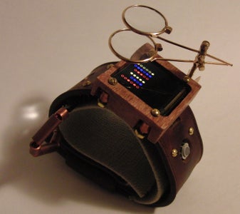
Step 12: Steampunking the Watch


Copper tubing is your friend when you want to give your watch a steampunk look. Spacers for the screws were made with 1/4" OD copper tube cut to about 0.26" length, you may need to try a few times to get the right length (I had to), but you can use the extra pieces in the cover for the battery wires. To cover the battery wires thread the wire through the small pieces of copper tube until you have covered up to the connector.
Magnifying lenses like the ones in the picture make a great addition to the look. You may need to remove one of the spacers to allow them to clip onto the screw or you can glue or solder the lenses to one of the spacers.
Step 13: Extensions: Range Finding


One of the attachments for the Arduino Watch is an ultrasonic range finder. This one is a Maxbotix LV-EZ2 (from SparkFun) and the watch is reading the pulse width modulated signal from the sensor.
In future versions I may route the output to a vibrating motor or speaker to allow for someone with visual impairment to use the range finder as a cane.
Step 14: Extensions: Temperature Sensing


With the temperature sensing glove attachment the Arduino Watch can give temperature warnings to the user i.e. warning that the drink is too hot or that there is a fire behind a door.
I'll be posting a separate short Instructable on how to make the glove but the sensors used are the one-wire Dallas 18B20 sensors.
Step 15: Wear and Enjoy!

Now that you have your Arduino Watch wear it and enjoy!


