

Introduction: Arduino Wireless Weather Station


In this Instructable I am going to show you how to build a Wireless Weather Station with a big 3.2" Color TFT display using Arduino. Building a Wireless Weather Station is a great learning experience. When you finish building this project you will have a better understanding of how wireless communucations work, how sensors work, and how powerful the Arduino platform can be. With this project as a base and the experience gained, you will be able to easily build more complex projects in the future.
A Weather station is a device that collects data related to the weather and enviroment using many different sensors. We can measure many things like:
- Temperature
- Humidity
- Wind
- Barometric Pressure
- UV index
- Rain
In the Weather Station that we are going to build we are going to measure Temperature and Humidity in two locations and display the current date and time. Building a weather station is extremely easy. But can a maker build a unit with a color TFT display and features that match those of a commercial unit? The answer is YES! With the power of open source software and hardware, one can build this impressive weather station easily!
The project consists of two parts, the transmitter and the receiver.
The transmitter measures the temperatutre and the humidity and send the data wirelessly to the receiver.
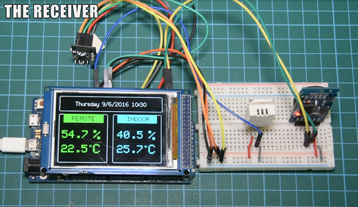
The receiver, measures the temperatutre and the humidity, receives the data from the remote sensor and displays everyting in big color tft display.
Let's build this project!
Step 1: Get All the Parts
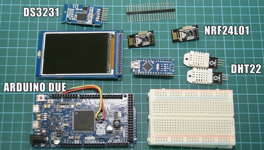
The parts needed in order to build this project are the following:
Arduino Due ▶ http://educ8s.tv/part/ArduinoDue
Arduino Mega ▶ http://educ8s.tv/part/ArduinoMega
Arduino Nano ▶ http://educ8s.tv/part/ArduinoNano
3.2" TFT display ▶ http://educ8s.tv/part/32TFT
DHT22 ▶ http://educ8s.tv/part/DHT22
NRF24L01 ▶ http://educ8s.tv/part/NRF24L01
DS3231 RTC ▶ http://educ8s.tv/part/DS3231
Breadboard ▶ http://educ8s.tv/part/SmallBreadboard
Wires ▶ http://educ8s.tv/part/Wires
Header Pins ▶ http://educ8s.tv/part/HeaderPins
Xiaomi Powerbank ▶ http://educ8s.tv/part/Powerbank
The cost of the project is around 40$. You can reduce the cost of the project by 5$ if you use the Arduino Mega instead of the Arduino Due. I choose to use the Arduino Due for the receiver because it is very fast and it has a lot of memory. This is going to be very useful in the future as we add more and more features to the project.
Step 2: Temperature and Humidity Sensor - DHT22

The DHT22 is a very popular Temperature and Humidity sensor. It is cheap, easy to use and the specification claims good precision and accuracy.
The DHT sensors are made of two parts, a capacitive humidity sensor and a thermistor. There is also a chip inside that does some analog to digital conversion and outputs a digital signal with the temperature and humidity. The digital signal is fairly easy to read using any microcontroller.
Characteristics of the DHT22
- Low cost
- 3 to 5V power and I/O
- 2.5mA max current use during conversion
- 0-100% humidity readings with 2-5% accuracy
- -40 to 125°C temperature readings ±0.5°C accuracy
- Slow
The connection with Arduino is extremelly easy. We connect the sensor pin with the + sign to the 5V or the 3.3V output of the Arduino. We connect the sensor pin with the - sign to GROUND. Lastly we connect the OUT pin to any digital pin of the Arduino.
In order to use the DHT22 sensor with Arduino we have to use the DHT library.
Step 3: The DS3231 Real Time Clock Module

The DS3231 real time clock module is as its name suggest a Real Time Clock. Using its battery it can keep time for years since it has minimal power consumption.
The DS3231 is a low-cost, extremely accurate I2C real-time clock (RTC) with an integrated temperature compensated crystal oscillator (TCXO) and crystal. The device incorporates a battery input, and maintains accurate timekeeping when main power to the device is interrupted. The integration of the crystal resonator enhances the long-term accuracy of the device as well as reduces the piece-part count in a manufacturing line.
The RTC maintains seconds, minutes, hours, day, date, month, and year information. The date at the end of the month is automatically adjusted for months with fewer than 31 days, including corrections for leap year. The clock operates in either the 24-hour or 12-hour format with an AM/PM indicator. Two programmable time-of-day alarms and a programmable square-wave output are provided. Address and data are transferred serially through an I2C bidirectional bus.
The cost of the module is extremely low, it costs around 2$ including the battery! We are going to use it in order to keep time in our Weather Station Project.
Step 4: NRF24L01+: Wireless Modules


The NRF24L01 module is a low cost bi-directional transceiver module. The cost of it is less than 3$! It operates at the 2.4GHz band and it can achieve at a data rate of 2Mbits! Impressive isn’t it? It uses the SPI interface in order to communicate with Arduino, so it is very easy to use with it. We have to connect 7 of the 8 pins of the module in order to make it work with Arduino.
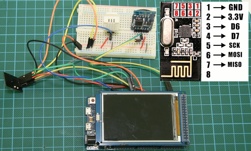
Unfortunately we can’t plug the module in the breadboard so we are going to use male to female wires in order to connect the module to Arduino. Pin number 1 of the module is GND. You have to connect it to Arduino Ground. The next pin is Vcc. You have to connect it to the 3.3V output of the Arduino Uno. Be careful! Do not connect it to 5V or you will destroy your module! The third pin is named CE and you can connect it to any digital pin you like. In this example I am going to connect it to digital pin 7. Pin 4 is CS and you can connect to any digital pin as well. I am going to connect to digital pin 8. The next pin is SCK which goes to digital pin 13 of the Arduino Uno. The next pin is MOSI which goes to digital pin 11 and the last pin in MISO which goes to digital pin 12. That’s it!
In order to be easy to use the module with Arduino we have to use the following library:
https://github.com/TMRh20/RF24
If you haven't used the NRF24L01+ modules so far, please check the attached video in order to see how to use it by building a simple project. It will help you understand the way it works.
Step 5: Building the Trasmitter


Let’s first build the transmitter. It is very simple.
For the transmitter we use:
- An Arduino Nano
- A DHT22 sensor
- A NRF24L01+ wireless module
- A breadboard
- Some wires
We connect the output pin of the sensor to digital pin 4 of the Arduino Nano. We connect the Ground and Vcc and we are ready. All we have to do now is to connect the NRF24L01 wireless module.
Please attach it using the pins that are shown in the third image. For more details, please watch the detailed video I have attached in the previous step.
That's it, your transmitter is ready. Let's now move on to the receiver.
Step 6: Building the Receiver


In order to build the receiver we need the following parts:
- An Arduino Due or a Mega
- A DS3231 Real Time Clock module
- A DHT22 Temperature and Humidity Sensor
- A NRF24L01+ Wireless module
- A 3.2" Color TFT display
- A breadboard
- 7 header pins
- Some wires
At first we bend 7 header pins and we place them at some of the Arduino Due pins. We need one to Ground and one to 3.3V. We need two at the I2C pins. We need the remaining 3 to digital pins from 6 to 8. We also have to solder three wires to the hardware SPI pins of the Arduino Due pins. We need MOSI, MISO and SCK. Check the diagram carefully. We connect the wires to the header pins and we are ready to attach the display.
Connecting the DS3231
the VCC pin on Arduino’s 3.3V output
the GND pin to Arduino’s GND and
the SDA (Serial Data Line) pin to Arduino’s SDA pin and
the SCL (Serial Clock Line) pin to Arduino’s SCL pin
Connecting the DHT22 Sensor
the VCC pin on Arduino’s 3.3V output
the GND pin to Arduino’s GND and
the output pin to Arduino's digital pin 8
Connecting the NRF24L01 module
the GND pin to Arduino’s GND
the VCC pin to Arduino 3.3V
the 3rd pin to Arduino's digital pin 6
the 4th pin to Arduino's digital pin 7
the 5th pin to SCK pin that we have soldered
the 6th pin to MOSI pin that we have soldered
the 7th pin to MISO pin that we have soldered
Step 7: The Transmitter Code
First of all, we have to download the RF24 library in order to make our life easier when we work with the NRF24L01 wireless modules. We also need the DHT library for the DHT22 sensor.
NRF24L01 Library: https://github.com/TMRh20/RF24
DHT22 Library: https://github.com/adafruit/DHT-sensor-library
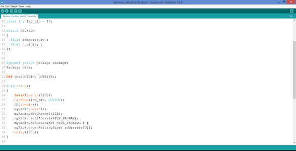
Let’s first see the Transmitter code. It sends out a simple data structure which contains two floats, the temperature and the humidity.
In order to establish a communication link we have to create a “pipe” between the two modules. That pipe needs to have an address. Both modules have to write and read from the same pipe in order to communicate. That’s the first thing we define in our code, we set the pipe address to “0”. Next we define the channel at which we want to communicate with the other module. The NRF24L01 chip supports 126 different channels. Both modules need to use the same channel in order to communicate with each other. In this example I am using channel 115. Next, I define that I want to use the maximum transmitting power that the module offers. It uses more power but extends the range of the communication. Next we define the data rate of the transmission. I set it to 250Kbs which is the lowest possible data rate in order to achieve better range. The next step is to open the pipe in order to write to it later.
In the loop function, we read the temperature and humidity values from the sensor, we save that data to the data structrure and then we send the data structure by writing the data structure to the pipe. That's it. You can find the code attached in this intstuctable.

Step 8: The Receiver Code


Let’s now see the receiver code. We need 4 libraries.
First we have to download the library for the display from this link:
DISPLAY Library: https://github.com/Bodmer/TFT_HX8357_Due
After downloading the library you have to open the User_Setup.h file comment line 13 and uncomment line 14 because the display we have is using the HX8357C driver. Now we can continue with the 3 other libraries. We need one library for the Real Time clock, one for the DHT22 sensor and lastly one for the Wireless module.
NRF24L01: https://github.com/TMRh20/RF24
DHT22: https://github.com/adafruit/DHT-sensor-library
DS3231: https://github.com/SodaqMoja/Sodaq_DS3231
Let's take a look at the code.The first thing we have to do is to set the time to the real time clock module if it is not already set. In order to do it, enter the current date and time in then setRTCTime function uncomment the setRTCTime call of the function on line 54 and upload the program to Arduino. Now the time is set. But, then we have to comment setRTCTime call of the function again and upload the program to Arduino once more.
The code of the receiver works like this. In the setup function we initialize all the sensors and the modules and we print the User Interface. Then at the loop function we continuously check for new wireless data. If there is new data we save that data in variables and print them on the display. We read the temperature and the humidity once a minute and we only update the display if there is a change in the values. This way we reduce flickering of the display even more! I have also prepared a version of the code with the temperature displayed in degrees Fahrenheit. You can find both version of the code attached on this instructable.
Step 9: Testing the Project


The last step to power up everything and see if everything is working as expected. If so, at the top of the display the current date and time is displayed. At the bottom of the display you can see the temperature and the humidity from both the remote and the local sensor.
If there is no data displayed for the remote sensor, move the transmitter closer, it be out of range. If the problem persists, check all the connections one more time, there must be something wrong there.
As you can see, this project is a great demonstration of what open source hardware and software is capable of. Within a few hours one can build such an impressive project! Of course, this is a just the beginning. We can add many more features to the project. I will soon add a button, so we can display graphs, and have different modes. We can also add more sensors, data logging, internet connection and so on. We are using the Arduino Due, so we have plenty of memory to implement many more things. I would love to hear your opinion on this project. How do you want to see it evolve? Please post your comments or ideas in the comments section below!
If you want more details, watch the YouTube Video in the introduction or visit mywebsite. Thanks for taking a look!


