

Introduction: Arduino and Plotly Based Seismograph


This is a simple arduino based Seismograph that send the data it collects to a python script that graphs the data live and can export it to plotly. This seismograph is fairly sensitive, it can detect a person jumping beside it. The seismograph is mostly made of wood and uses a simple arduino circuit to record the data. You can see a plotly graph of me jumping beside it here.
Step 1: Tools and Materials
Materials
- One 7 1/2" X 18 1/2" Piece of 3/4" or 1/2" plywood
- Two 16 1/2" Pieces of 2 1/2 X 3/4" wood
- Two 7 1/2" Pieces of 2 1/2 X 3/4" wood
- One 13" Piece of 2" X 2"
- One 4" Piece of 2" X 2"
- Screw
- 1/8" X 18" of steel rod
- A Ball
- Hard Drive Magnet
- Fishing Line or Thin Cable
- 2" X 2" piece of 1/4" metal
- Gravel
- Arduino
- Breadboard
- LM6386-N
- Jumper Wires
- Python with pygame and plotly library(See last step)
Tools
- Hot Glue Gun
- Drill and Drill Bits
- Bench Grinder
- Center Punch
Step 2: The Base

To make the base start by lining up the four 2 1/2" X 3/4" pieces of wood to make a rectangle as shown. Next drill a pilot hole 3/8" from the edge of the shorter pieces of wood and into the ends of the longer pieces. Finally, screw the four pieces together using the pilot holes tho make a rectangle.
Step 3: The Arm


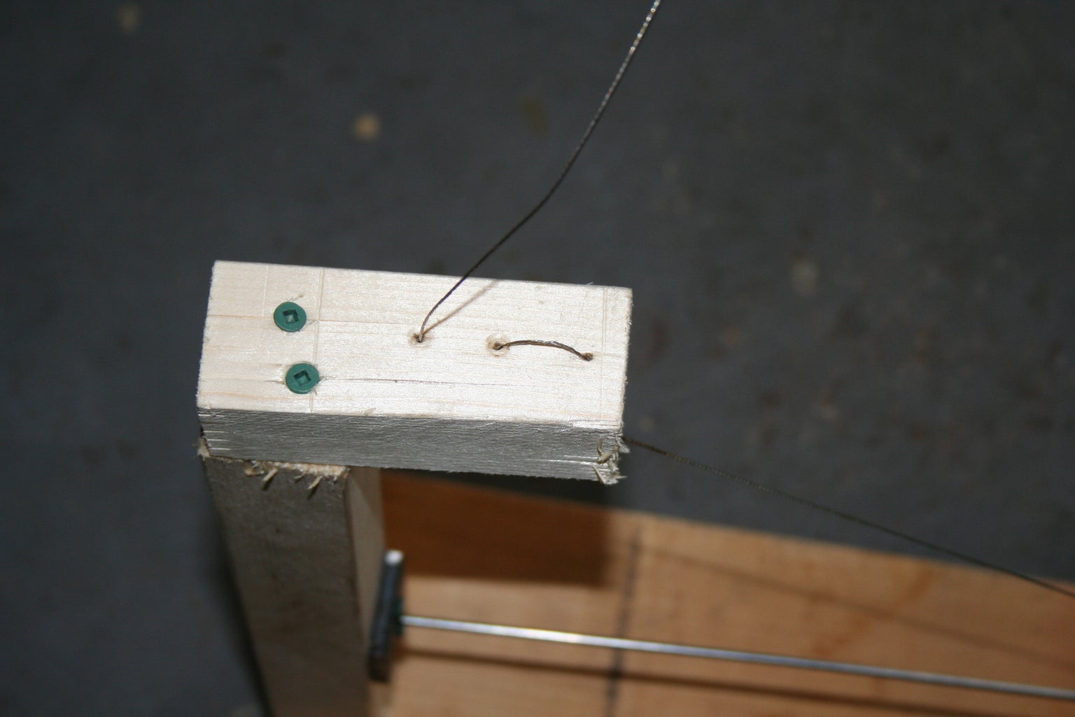
To make the arm start by drilling three 1/16" holes about 3/4" apart in the center of the 4" piece of 2X2(See second picture). Next drill a pilot hole in the top of the 13" 2X2 and at the opposite end of the 4" 2X2 from the three holes. Finally, screw the two pieces using the pilot hole to make a L shape.
Step 4: The Hinge
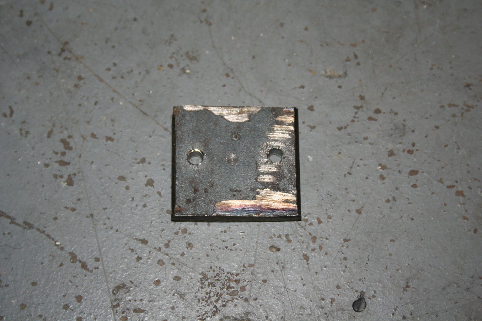


To make the hinge start by drilling a hole with a 7/64" bit as deep as the pointed part of the bit in the center of the piece of metal. Then drill a hole that is big enough for a screw to pass though about 1/4" away from the edge and repeat for the opposing edge. Lastly screw the metal plate into the arm 4" from the bottom(see last picture).
Step 5: Assembling the Base


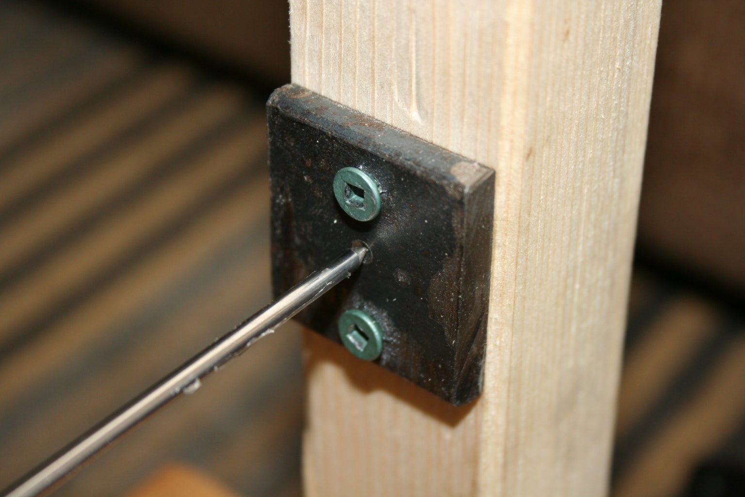
To assemble the base just screw the L shaped arm to the center of the shorter edge of the piece of plywood using pilot holes.
Step 6: The Boom

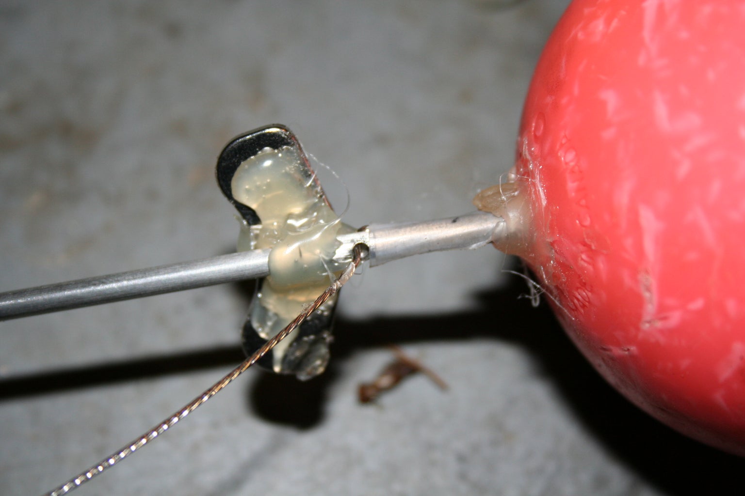


Start by sharping one end of the 1/8" rod with a bench grinder or Dremel. Next, using the center-punch mark a hole about 2 1/2" from the unsharpened end of the rod and then drill a 1/16" hole though the rod(see second picture). Then cut off 2 1/2' of thin cable or fishing line and feed about an inch though the hole you just drilled and then bend the one inch part of the wire so it is parallel to the rod and duct tape it into place(second picture). After that, hot glue the hard drive magnet in place as shown in the second and third picture. Now we will start making the counter weight, first cut the ball in half and drill a 1/8" hole in the center of one of the halves. Next slide the unsharpened end of the rod though the hole in the ball until it reaches the the duct tape holding the cable in place and then hot glue the half ball in place(second last picture). Finally, fill the half ball on the rod with gravel or sand and hot glue the two halves together.
Step 7: The Feedback System


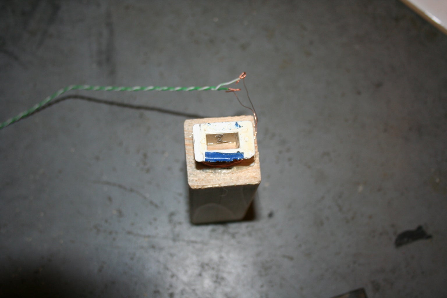
To make the feedback system, start by following this instructable up to step three. Next feed the cable from the boom though the holes in the arm as shown in the second picture and then line the pointed end of the boom up with the shallow hole in the metal plate as shown in the third picture and adjust the cable until the boom is level and adjust the top part of the arm by loosening the top screw and moving the top of the arm until the boom is straight. Lastly measure how high off the ground the magnet on the boom is and subtract the height of the transformer plus 1/8" and cut a 2X2 that length and then hot glue the transformer to one end of the 2X2.
Step 8: Final Assembly


Begin by lining up the 2X2 with the transformer with the magnet on the boom and marking that spot with a sharpie. Next, drill two pilot holes in the area you just marked out and in the end of the 2X2 and then screw the 2X2 in to place using the pilot holes. After that, screw the plywood platform to the 2 1/2" X 3/4" base using a screw in each corner.
Step 9: The Electronics


Begin by attaching jumper wires to the transformer and then hook the arduino up as shown in the first picture replacing the microphone with the wires from the transformer.
Step 10: The Arduino Sketch


Once you have uploaded the sketch to the Arduino open the serial monitor, if all you see is X when the seismograph is not moving then you don't need to change anything(picture 3). If are alternating numbers on the serial port(picture 2) then replace 581 in the if statement with the larger of the two numbers on the serial port and 580 with the smaller.
Attachments

Step 11: The Python Script


To use the python script you will need pygame and plotly libraries and a plotly account. To make the script work you just have to replace "serial port" on line three with the serial port your arduino is connected to which can be found in the bottom left hand corner of the arduino ide. You will also have to replace "user name" with your plotly user name and API key with your plotly API key found here.
Attachments

First Prize in the
Data Visualization Contest

Participated in the
Arduino Contest

Participated in the
Full Spectrum Laser Contest


