

Introduction: Arduino and Touchpad Tic Tac Toe


Or, an exercise in input and output multiplexing, and working with bits. And a submission for the Arduino contest.
This is an implementation of a tic tac toe game using a 3x3 array of bicoloured LEDs for a display, a simple resistive touchpad, and an Arduino to tie everything together.
To see how it works, check out the video:
What this project requires:
Parts and consumables
One perf board (or strip board)
Nine bicoloured LEDs, common cathode
Nine identical resistors, in the 100-220 ohm range
Six identical resistors, in the 10kohm - 500kohm range
One single pole, double throw switch
A bunch of header pins
A bunch of electrical wire
One small square sheet of transparent acrylic, ~ 1 mm thick, 8 cm on the side
Clear sticky tape
Heatshrinks (optional)
All of the above are quite common items, total cost should not exceed USD$20.
Tools
One Arduino setup (Arduino Duemilanove, Arduino IDE, computer, USB cable)
Usual electrical tools (multimeter, solder solder gun, wire snips, wire cutter)
Everything Arduino related can be found at http://www.arduino.cc.
On with the build!
Step 1: Wiring Up the LED Matrix


For an LED to light, both its leads must be connected. If we were to dedicate a pair of pins to each of the 18 LEDs (9 red, 9 green), we'd quickly run out of pins on the Arduino. However, with multiplexing, we'll be able to address all the LEDs with merely 9 pins!
To do this, the LEDs are wired up in a crossbar fashion, as shown in the first figure. The LEDs are grouped in columns of threes, and their cathodes are grouped in rows of sixes.
By setting a particular anode line high, and a particular cathode line low, and having a high impedance on all the other anode and cathode lines, we can select which LED we want lit up, as there is only one possible path the current can take.
For instance, in the second figure, setting the green anode 1 line high, and the cathode 1 line low, the bottom left green LED lights up. The current path in this case is shown in blue.
But what if you want to light up more than one LED on different lines? We'll use persistence of vision to achieve this. By selecting pairs of LED lines very very quickly, it gives the illusion that all the selected LEDs are lit at the same time.
Step 2: LED Matrix Layout


The circuit diagram below shows how the LEDs are physically wired up (G1-G9: green LEDs, R1-R9: red LEDs). This diagram is for single red and green LEDs, if you are using bicoloured common cathode red/green LEDs, there's only one cathode leg per red/green pair that you have to wire up.
The red and green anode lines go into the PWM pins of the Arduino (pins 3, 5, 6, 9, 10, 11 on the Duemilanove), so that we can have effects like fading later on. The cathode lines go into pins 4, 7 and 8.
Each of the cathode and anode lines have 100 ohm resistors for protection.
Step 3: Addressing the LED Matrix
For the tic tac toe code, we'll need to be able to store the following information about the LEDs:
- whether an LED is lit or not
- if lit, whether it's red or green
One way of doing this is to store the state in a 9-cell array, using three digits to represent the state (0 = off, 1 = red on, 2 = green on). Everytime we need to check on the states of the LED, for example, to check if there's a win condition, we'll need to cycle through the array. This is a workable method, but rather clunky.
A more streamlined method would be to use two groups of nine bits. The first group of nine bits stores the on-off status of the LEDs, and the second group of nine bits stores the colour. Then, manipulating the LED states simply becomes a matter of bit arithmetic and shifting.
Here's a worked example. Let's say we draw our tic tac toe grid graphically, and first use 1s and 0s to represent the on-off status (1 is on, 0 is off):
000
000 = matrix with bottom left LED lit
100
100
010 = matrix with diagonal LEDs lit
001
If we enumerate the cells from the bottom left, we can write the above representations as a series of bits. In the first case, that would be 100000000, and in the second case, it would be 001010100. If we think of these as binary representations, then each series of bits can be condensed into a single number (256 in the first case, 84 in the second case). So instead of using an array to store the state of the matrix, we can just use a single number!
Similarly, we can represent the colour of the LED in the same way (1 is red, 0 is green). Let's first assume all the LEDs are lit (so the on-off status is represented by 511). The matrix below will then represent the colour state of the LEDs:
010 green, red, green
101 red, green, red
010 green, red, green
Now, when displaying the LED matrix, we just have to cycle through each of the bits, first in the on-off state, and then in the colour state. For example, let's say our on-off state is 100100100, and the colour state is 010101010. Here's our algorithm for lighting up the LED matrix:
Step 1. Do a bitwise addition of the on-off state with a binary 1 (ie bit masking).
Step 2. If it's true, the LED is lit. Do now a bitwise addition of the colour state with a binary 1.
Step 3. If it's true, light up the red LED. If it's false, light up the green LED.
Step 4. Shift both the on-off state and colour state, one bit to the right (ie bit shifting).
Step 5. Repeat Steps 1 - 4 until all nine bits have been read.
Note that we're filling the matrix backwards - we start with cell 9, then proceed back down to cell 1.
Also, the on-off and colour states are stored as an unsigned integer type (word) instead of a signed integer type. That's because in bit shifting, if we're not careful, we might inadvertenly change the sign of the variable.
Attached is the code for lighting up the LED matrix.
Attachments

Step 4: Constructing the Touch Pad

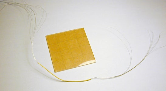


The touchpad is constructed from a sheet of thin acrylic, large enough to overlay over the LED matrix. Then, tape down the row and column wires onto the acrylic sheet, using clear tape. Clear tape is also used as the insulating spacer between the wires, at the intersections.
Be sure to use clean tools, to prevent finger grease from getting onto the sticky side of the tape. Fingerprint stains not only look ugly, but make the tape less sticky.
Trim off one end of each of the lines, and solder the other end to a longer wire. Solder a resistor in-line with the wires, before soldering on connectors. The resistors used here are 674k, but any value between 10k and 1M should be fine.
The connections to the Arduino are made using the 6 analog pins, with pins 14-16 connected to the wire grid rows, and pins 17-19 connected to the columns.
Step 5: The Touch Pad - How It Works


The concept for this touch pad is simple. It is essentially a wire grid, with three bare wires running in rows, and three bare wires running in columns above the rows. At each intersection point is a small square of insulation that prevents the two wires from touching. A finger touching the intersection will make contact with both wires, resulting in a huge, but finite resistance between the two wires. A small current, but detectable, current can therefore be made to flow from one wire to the next, via the finger.
To determine which intersection was pressed, the following method was used:
Step 1: Set all the column lines to OUTPUT LOW.
Step 2: Set the row lines to INPUT, with the internal pullups activated.
Step 3: Take an analog read on each row line until the value drops below a given threshold. This tells you in which row the pressed intersection is.
Step 4: Repeat Steps 1-3, but now with the columns as inputs and the rows as outputs. This tells you which column the pressed intersection is.
To minimise the effects of noise, a number of readings are taken and then averaged. The averaged result is then compared against a threshold.
Since this method just checks against a threshold, it's not suitable for detecting simultaneous presses. However, since tic tac toe proceeds in turns, reading a single press is sufficient.
Attached is a sketch illustrating how the touchpad works.
As with the LED matrix, bits are used to represent which intersection was pressed.
Attachments
Step 6: Putting Everything Together

Now that all the individual components are done, it's time to put them all together.
Overlay the wire grid on the LED matrix. You may need to reorder the pin numberings in the LED matrix code to get it synchronised with the wire grid sensor. Secure the wire grid in place with fastenings or adhesives of your choice, and stick on a nice playing board.
Add a switch between pin 12 and ground of the Arduino. This switch is to toggle between 2 player mode, and 1 player mode (vs the microcontroller).
Step 7: Programming Tic Tac Toe
Attached is the code for the game.
Let's first break down the tic tac toe game into its various steps, in the two player mode:
Step 1: Player A picks an unfilled cell by touching an intersection.
Step 2: The LED for that cell lights up with the colour A.
Step 3: Check to see if Player A has won.
Step 4: Player B picks an unfilled cell.
Step 5: The LED for that cell lights up with colour B.
Step 6: Check to see if Player B has won.
Step 7: Repeat 1-6 until there's a win condition, or if all the cells are filled.
Reading the cells:
The program loops between reading the grid and displaying the LED matrix. As long as the grid sensor does not register a non-zero value, this loop will continue. When an intersection is pressed, the Pressed variable stores the position of the pressed cell.
Checking if the cell is unfilled:
When a position reading is obtained (variable Pressed), it is compared against the current cell status (stored in the variable GridOnOff) using a bitwise addition. If the Pressed cell is unfilled, then proceed to light up the LED, otherwise return to reading the cells.
Toggling the colours:
A boolean variable, Turn, is used to record whose turn it is. The LED colour chosen when a cell is picked is determined by this variable, which alternates each time a cell is chosen.
Checking for a win condition:
There are only 8 possible win conditions, and these are stored as word variables in an array (winArray). Two bitwise additions are used to compare a player's filled cell positions to the win conditions. If there's a match, then the program displays a win routine, after which it starts a new game.
Checking for a draw condition:
When nine turns have been recorded and there is still no win condition, then the game is a draw. The LEDs are then faded out and a new game is started.
Switching to one player mode:
If the switch is in the on position, the program goes into one player mode, with the human player starting first. At the end of the human player's turn, the program simply picks a random cell. Obviously, this isn't the smartest strategy!
Attachments
Step 8: Remarks and Further Improvements
Here a video showing the one player mode, with the program playing totally random moves:
The program shown here is only a minimal, bare bones version. Many other things can be done with this:
1) Lighting up LEDs three at a time
The current code displays only one LED at once. However, with the wiring shown here, it's possible to light up all the LEDs connected to one cathode line at the same time. So, instead of cycling through all the nine positions, all you need to do is cycle through the three cathode lines.
2) Use interrupts to display the LEDs
Depending on the LED display routine and the amount of processing, the LEDs may show some degree of flickering. By using interrupts, the timing of the LEDs can be controlled precisely and would lead to a smoother display.
3) A smarter computer player
The currrent code takes up only a few kb, leaving quite a bit more for the implementation of a smarter computer tic tac toe player.
Hope you've enjoyed reading this instructable as much as I had fun working on it!
Participated in the
Arduino Contest


