

Introduction: Arduino Animatronics- Make Your Awesome Costumes More Awesome!


p { } I'll show you how to make a neat little compact Arduino servo controller board with built in servo connectors that is perfect for costuming and haunted house applications. There are multiple code examples, wiring diagrams and I'll show you how to connect sensors and even how to connect two controllers using wireless radios.
Here's a little movie clip of what is easily possible- an animatronic Predator cannon with laser sight, cannon firing sound and head tracking motion control.
Here's an Iron Man hand repulsor with servo to open the forearm missile compartment. Follow along and find out how to make your awesome costumes more awesome...
Update: My instructable for showing how to make an animatronic Stargate helmet is here-
https://www.instructables.com/id/Animatronic-Stargate-helmet/
I've also created an animatronics forum where people can go to get help with their costume and prop projects. I get so many messages for specific project help from people that I decided to create a dedicated forum where everyone can get help and share ideas!
Note- While this instructable is written for the beginner, this tutorial assumes you know how to use a soldering iron and other assorted tools like wire strippers and wire cutters. Please be sure to take proper safety precautions, wear safety glasses when using cutting tools and have adequate ventilation when soldering. If you aren't yet comfortable soldering small surface mount components don't fret- I've posted links in the reference section that will help you become a soldering champ in no time.
Step 1: First You Need an Arduino


Arduino is an open source microcontroller- essentially it is a small computer with an easy to use cross platform programming language. It allows you to create interactive objects based on sensory inputs (physical computing.) You can use it to do something simple like make an LED fade or have a servo move when you push a button or have it do something very complex like control a robot by processing sensor inputs, send the inputs to a computer over a wireless network and then send commands back to the robot. The applications are really limited only by your imagination and there are thousands of examples of cool projects all over the Web. There are several books about Arduino and its capabilities and I've listed a few in the reference section.
Which Arduino to use?
There are several variations of the Arduino controller available so which one do you use? It depends on your application. Some have more input pins than others if you need a lot of sensor inputs. For the purposes of this instructable you really can use any Arduino you like as the information presented applies to most every version. Here is a spreadsheet that shows most of the current variations available-
https://spreadsheets.google.com/ccc?key=0AsCUiP6WbJIvcG8xalA3QVdmb3JVT0ptWE9VNC02WEE&hl=en#gid=0
If you are going to use an Arduino Uno or Mega or any Arduino that has built in USB then you can skip to the getting started section.
Building a servo board
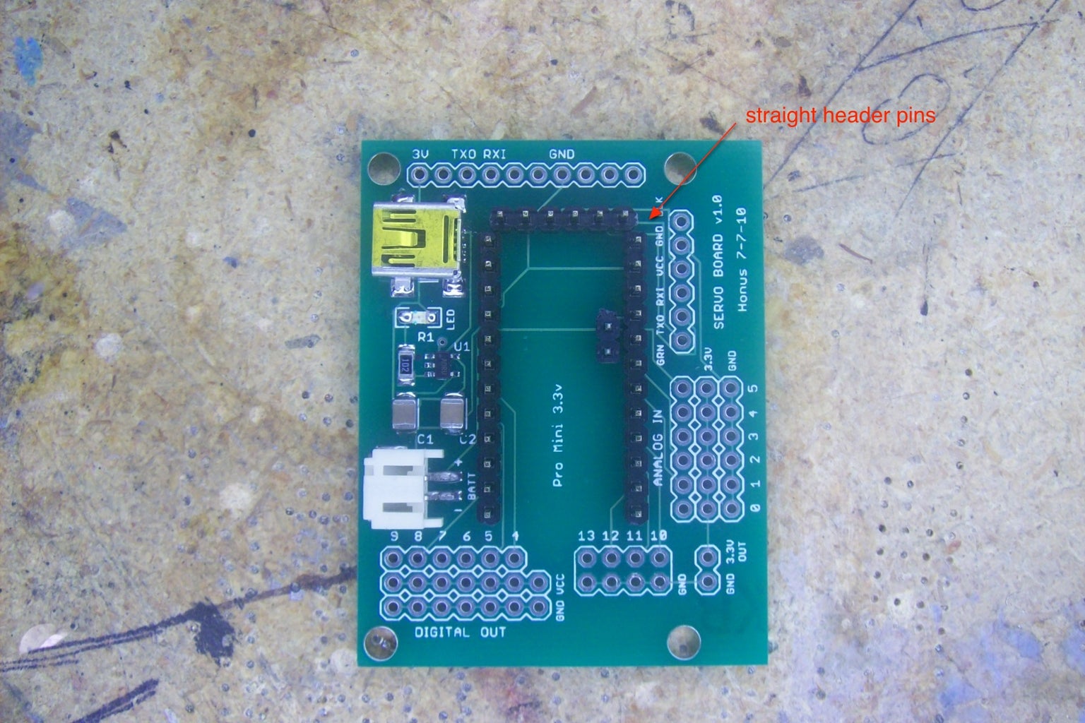
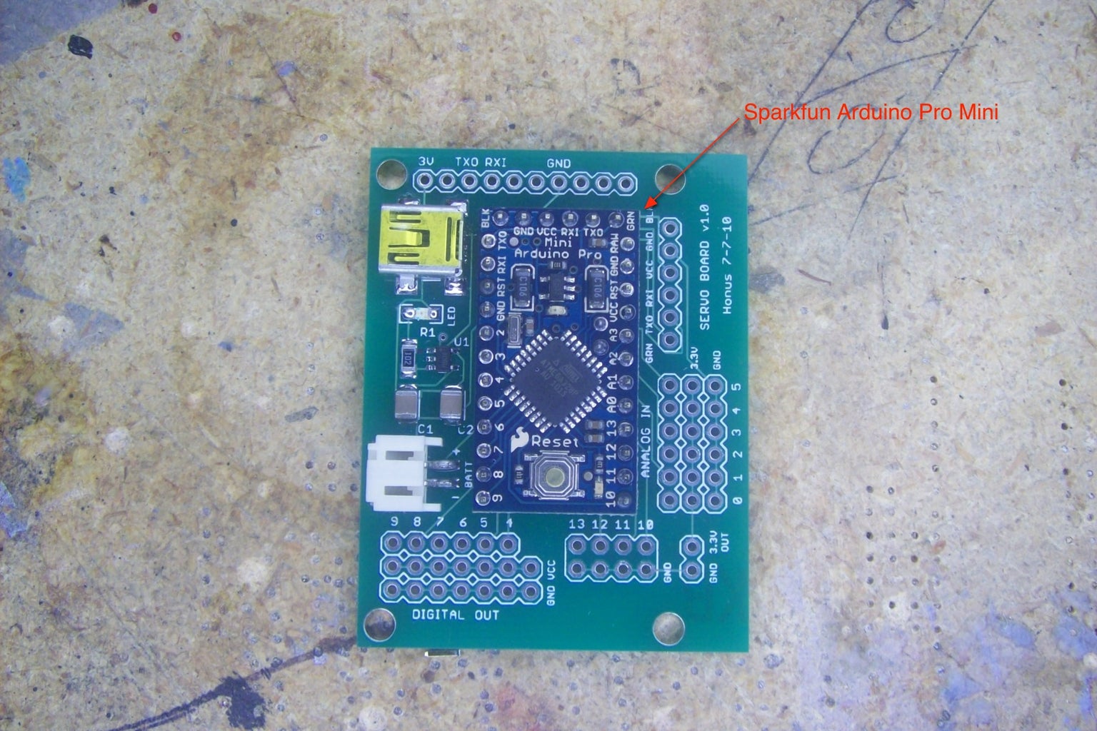
Since my focus is mainly on costume building I decided to use the Sparkfun Arduino Pro Mini and then build a compact servo application board for it that has multiple servo outputs, analog inputs and digital outputs. I also added a socket for an Adafruit Xbee wireless radio adapter as well as a charging circuit for a single cell LiPo battery to power the controller.
The reasons I really like the Pro Mini are its very small form factor, low cost and low power requirements. It operates on 3.3V, which means it can be powered by a single LiPo cell and that makes it easy when connecting sensors that run on 3.3V.
The latest version servo board has eight servo outputs, four digital outputs and six analog inputs. The servo outputs are also digital outputs- they're just configured to make it really easy to connect hobby servos. The earlier version seen in the photos has six servo outputs. Each servo output has three pins- ground, power and signal. The analog inputs are configured the same way- each input has three pins- ground, power and signal. This configuration makes it super easy to connect individual sensors. The board measures 1.75" x 2.30" so it's pretty small.
The board has a circuit for charging the LiPo cell that powers the controller. There is a mini USB port for 5v input power. Simply connect the battery and then plug in a USB cable and the battery will automatically charge. There is a charging indicator- the LED is on when the battery is charging and then it will automatically turn off when the battery is fully charged.
The mini USB port will also power the controller, even without a battery connected. The mini USB port is only used as a power source connector while charging or during times when a LiPo battery is not available- there is no data transmission using the mini USB port and you are limited by the amount of power a USB port can provide.
Code is uploaded to the controller using a USB to serial adapter (more on this later.) This adapter can also power the controller over USB without the need to connect the battery. This comes in really handy when you're testing code and you want to power the controller without having to connect the LiPo battery.
I'm providing all the necessary EAGLE files so people can modify the design to suit their own needs.
EAGLE can be downloaded here- http://www.cadsoftusa.com/
Attachments

Step 2: Building the Controller


Tools and materials
Soldering iron- A good quality soldering iron is a must. I received an Aoyue 2900 soldering station a couple years ago for Christmas and it's been great. You won't believe the difference once you start using a good soldering iron.
http://sra-solder.com/product.php/6363/22
I also use a small tip for soldering small surface mount components-
http://sra-solder.com/product.php/6397/0
Wire cutters/wire strippers- Small flush cutters are the best. If you don't have wire strippers or cutters then these will work well-
http://www.adafruit.com/index.php?main_page=product_info&cPath=8&products_id=152
http://www.adafruit.com/index.php?main_page=product_info&cPath=8&products_id=147
Tweezers- Get some small tweezers to work with surface mount components. Here's an inexpensive set-http://sra-solder.com/product.php/6409/79
Magnifiers- Being able to see what you're working on makes a world of difference.
http://www.adafruit.com/index.php?main_page=product_info&cPath=8&products_id=291
Multimeter- Most any multimeter will work. You don't need to spend big $$$. I personally own a Wavetek Meterman 16XL and it's great. If you don't already own a multimeter and are really getting into hobby electronics then this meter will probably do everything you could ever want-
http://www.adafruit.com/index.php?main_page=product_info&cPath=8&products_id=308
Servo board PCB-
http://batchpcb.com/index.php/Products/47581
Arduino Pro Mini- http://www.sparkfun.com/products/9220
USB mini-B connector- http://www.sparkfun.com/products/587
capacitors- 2 ea 1210 package 1uF SMD ceramic capacitors
http://us.element-14.com/kemet/c1210x105k5ractu/capacitor-ceramic-1uf-50v-x7r-1210/dp/94M5711
resistor- 1ea 1206 package 1K Ohm SMD resistor
http://us.element-14.com/welwyn/wcr1206-1k0fi/resistor-thick-film-1kohm-250mw/dp/98K2656
LED- 1 ea 1206 package SMD LED
http://us.element-14.com/vcc-visual-communications-company/vaol-s12rp4/led-2x1-5mm-red-133mcd-624nm/dp/27R0088
JST connector- 1 ea
http://www.sparkfun.com/products/8612
MAX1555 IC- 1 ea
http://www.sparkfun.com/products/674
http://us.element-14.com/maxim-integrated-products/max1555ezk-t/ic-battery-charger-li-ion-340ma/dp/59J2761?Ntt=MAX1555
Straight break away header pins - 2ea 40 pin row
These come in really handy so it's always good to get extras to have on hand
http://www.sparkfun.com/products/116
Female break away header pins- 2 ea 40 hole row
These also are super handy to have around
http://www.sparkfun.com/products/115
Single cell LiPo battery- 1ea (you can use any capacity you like.)
http://www.sparkfun.com/products/339
USB mini-B cable- 1 ea
Odds are you've already got one but if you don't here you go-
http://www.sparkfun.com/products/598
Assembling the servo board
The first thing to do is build the charging circuit. I usually start with the smallest components first. I've found the easiest way to solder SMD parts is to get a tiny bit of solder on your soldering tip and touch it to one of the component pads on the PCB. Then hold the component in place using tweezers and heat up the pad and component pin- this allows you to get the part attached to the board so you can check its alignment for the rest of the pads. Then simply solder each of the remaining pads. There is a great series of SMD soldering tutorials here- http://www.sparkfun.com/tutorials/36
Begin by soldering on the MAX1555 IC (labeled U1) -this can only go on one way. Next comes the LED- make sure to check the polarity as it is labeled on the PCB (the LED cathode is connected to one end of R1.) Then solder resistor R1 followed by the capacitors C1 and C2. These can be soldered on either direction. Next comes the mini USB connector- this one is a bit tricky as the pins are positioned nearly underneath the connector. Now solder on the JST connector. Make sure to double check your soldering job for these connectors as they receive a fair bit of mechanical stress.
Now test your charging circuit. Plug in a USB cable and check the voltage at the JST battery connector. It should read about 4.2-4.3V. Now connect the LiPo battery. If everything is OK the small LED should turn on, indicating the battery is charging. Disconnect the battery.
Now solder on the pins to connect the Pro Mini board. This is done by soldering on the break away straight header pins. First insert the long pin ends into the PCB, flip the board over and solder them in place. Double check your solder joints. Now flip the board over and place the Pro Mini board in place on top of the exposed pins and solder all the pins in place. Next solder the remaining straight pins into place in the digital out positions and the 3.3v port along the bottom of the board.
To finish the board solder all the female headers in place. The best way I've found to cut the female headers is to remove a pin where you want to make a cut- just yank the pin out the bottom using a pair of pliers. Then take wire cutters and cut through the opening left by the pin. Now take a file (or sandpaper) and smooth out the cut edge.
Make sure your board is getting power by plugging a USB cable into the mini USB port on the controller board. The red LED on the Arduino Pro Mini should light up.
That's it- your controller is ready to go!
Step 3: Getting Started


I really like these boards because you can see the LEDs light up when they are transmitting. You also need to make sure you have the latest FTDI drivers on your computer (you can get the most current drivers on the product web pages.)
Sparkfun FTDI Basic 3.3V breakout
http://www.sparkfun.com/products/10009
Adafruit FTDI friend
http://www.adafruit.com/index.php?main_page=product_info&cPath=18&products_id=284
You simply plug the FTDI Basic breakout into the programming socket on the controller board and connect it to a computer using a USB mini-B cable. Make sure to line up the GRN and BLK indicators.
If you're using an Arduino with built in USB then you don't need a USB to serial adapter- it's built into the Arduino board. Just connect it to a computer using a USB cable and you're good to go.
Programming environment
Now you need to download the Arduino software which is located here:http://arduino.cc/en/Main/Software
At the time of this writing I am using Arduino 0018. If you want to use the newer Arduino Uno or Mega2560 then you should use the latest release (0021 at this time) as the Uno and Mega2560 use a different type of USB to serial connection that is not supported by previous versions.
I also highly recommend reading the Arduino environment guide here:http://arduino.cc/en/Guide/Environment
The code you will use has several parts:
1. Program description/comments-
This is where you say what the program does
2. Variable declaration section-
This is where you assign input/output pins, etc.
3. Setup section-
This is where you set pins as inputs or outputs, etc.
4. Loop section-
This is the program that will run based on the conditions of your variables and setup sections.
When your program runs it will first define your variables, then execute the setup section once and will then execute the loop section over and over.
So what you do is open the Arduino software, add (or write) your code (called a sketch), verify (compile) your code, connect your Arduino to your computer, select the USB/serial connection, select the type of Arduino you're using then upload your code to the Arduino.
Here's the process-
1. Open Arduino window and add/write code-
Just open the Arduino program and paste the code example you want to use into the window (or write your own code.)
2. Verify-
Hit the verify button to compile your code. It will inform you if there are any errors with your code.
3. Connect board-
Connect the servo board to your computer using the USB to serial adapter- if you are using an Arduino with built in USB then just plug the Arduino directly into your computer.
4. Select connection-
This tells the USB to serial adapter which serial port you are going to use. The one to select is labeled beginning /dev/tty.usbserial so from the top menu go to Tools>Serial Port>/dev/tty.usbserial-(insert port name here)
5. Select board-
This tells the Arduino program which version board you are using. From the top menu go to Tools>Board>Arduino Pro or Pro Mini (3.3V, 8Mhz) w/ ATmega328 if you are using the Pro Mini servo board or choose the correct model Arduino.
6. Upload code-
Hit the upload button to send the code to your Arduino.
That's it!
Step 4: Making Connections- Motors, LEDs and Transistors


Inputs and outputs
Now we need to connect a few devices like servos, sensors and LEDs to our controller. The controller has inputs and outputs. Things like sensors and switches are input devices, while servos, LEDs and motors are output devices. The inputs and outputs are both analog and digital- a digital input is like a switch, so it's either on or off. Analog inputs are variable- it's more like a dimmer switch that gives you a range of values.
Digital outputs are similar- if the controller output pin is set HIGH then it's on. If it's set LOW, then it's off. This is great if you want to turn on a motor or LED. If you want to change the brightness of an LED or make a servo motor move then you want to make the controller output pin an analog output. This is done using PWM (pulsewidth modulation.) PWM simply allows the controller to fake an analog voltage output by setting the output pin HIGH and then setting the output pin LOW within a few microseconds or milliseconds of each other. If you pulse the pin HIGH for the same length of time you pulse it LOW you would get an average voltage of half the total voltage so the output pin would give you 1.6V instead of 3.3V. The amount of time the pin stays HIGH is called pulsewidth. The ratio of time for the pin to go from LOW to HIGH to LOW is called duty cycle. If you shorten the amount of time the pin stays HIGH relative to the amount of time it stays LOW you will effectively lower the output pin voltage. It really sounds more complicated than it is but this will come in really handy later on when you want make LEDs dim or make a servo move. Fortunately most of this complex stuff is done for you in the Arduino code libraries but it's still really good to know.
Sensors
There are all kinds of sensors- bend sensors, force sensitive resistors, accelerometers, potentiometers, joysticks, etc.
These analog sensors change their output voltage according to how you use them. In the examples we'll use button switches to turn things on and off and we'll use joysticks (potentiometers), bend sensors and accelerometers to make servos move.
When designing an animatronic system for costuming I try to match the type of sensor used with a specific body motion. Think about how the person wearing the costume is going to use it. Bend sensors are great if you want to make a LED dim or servo move by bending your finger. For even more control I can place a small joystick on a fingertip and use that to make a servo move. For a head tracking system that makes servos follow your head movement I use an accelerometer (from a Wii nunchuck) and I use fingertip switches to trigger sound effects. You'll see how these work in the examples.
Sparkfun has a good size momentary push button switch that is breadboard friendly-
http://www.sparkfun.com/products/9190
Here's the smaller version-
http://www.sparkfun.com/products/97
All of the sensors we'll use are connected to the Arduino input pins. A potentiometer is a device commonly used in an application like a stereo volume knob- it's a type of variable resistor. If you supply the potentiometer with 3.3V when you turn the knob the output voltage will range from 0 to 3.3V. A joystick is simply two potentiometers in a common housing- one for the X axis and one for the Y axis.
Sparkfun has a 10K potentiometer-
http://www.sparkfun.com/products/9939
They also have a couple of small joysticks-
http://www.sparkfun.com/products/9032
http://www.sparkfun.com/products/9426
A bend sensor is a resistor that changes its resistance value according to how much you bend it. By adding another resistor and creating a voltage divider, we can change the output voltage of the bend sensor to match the degree of bend. The only real drawback to bend sensors is that they don't have the wide range that a potentiometer has.
Sparkfun sells a bend sensor here-
http://www.sparkfun.com/products/8606
Accelerometers work by sensing a change in acceleration and then they alter their output relative to the change in acceleration. When you tilt an accelerometer it measures acceleration due to gravity- the more you tilt it the greater the change in output. Accelerometers are commonly used in video game controllers and cell phones.
A Wii nunchuck has a 3 axis accelerometer, joystick and two pushbuttons for $20.
Motors
Servos
Hobby servos are small geared motors that have a circuit board and potentiometer to control their rotation. This allows them to be able to move to an exact position relative to your input sensor signal. Most servos can move nearly 180 degrees and some can even do multiple rotations as well as continuous rotation. Servos have three wires- ground, power and signal. The signal wire (usually yellow or white) is connected to the Arduino output pin. The power and ground wires are connected to a separate power source, usually ranging anywhere from 4.8V to 6V. The reason for connecting servos to their own power supply is that motors generate a fair bit of electrical noise, which can cause glitches or a stuttering effect in their movement.
If you have an input sensor that generates an input voltage from 0-3.3V the Arduino takes that analog voltage and assigns it a value from 0-1023 using an analog to digital converter (ADC.) The code on the Arduino then tells the servo how far to move based upon the converted value. So if your sensor outputs 1.65V then you would get a reading of 511 and your servo would move half of its rotation. Many Arduino boards operate on 5V so the same sensor at the same position would read 2.5V and the servo would still rotate half way. A continuous rotation servo would rotate in one direction, stop as the sensor gave a 1.65V reading and then reverse direction as you caused to sensor to raise the input voltage.
Controlling a servo is done by PWM. You send a send a pulse to the servo on the servo signal line every 20 milliseconds. The pulsewidth tells the servo what position to move to. Most servos operate within a 1 to 2 millisecond pulse range so a 1 millisecond pulse tells the servo to move to the 0 degree position and a 2 millisecond pulse tells the servo to move to the 180 degree position. Any pulse between 1 and 2 milliseconds tells the servo to move to a position that is proportionate between 0 and 180 degrees.
I get all my servos here-
http://www.servocity.com
DC motors
Unlike most servo motors DC motors are best used when you need continuous rotation, especially when you want high RPM. Since DC motors can draw a fair amount of power they are connected to the Arduino output pin using a transistor or a PWM speed controller.
Pololu sells a large variety of small DC motors-
http://www.pololu.com/catalog/category/22
Stepper motors
I don't usually use stepper motors in my animatronic projects (at least not yet!) but I felt they are worth mentioning. Stepper motors allow for precise positioning as well as continuous rotation and speed control. The drawback to them is that they require a fair bit of electrical power and they're usually significantly larger and heavier than a servo of equal torque rating. Small stepper motors can be salvaged from old printers and scanners. Unlike DC motors stepper motors have multiple individual coils inside that must be activated in a proper sequence in order to get the motor to move. The Arduino controller is able to drive stepper motors using a specific driver chip or transistor array that is capable of energizing each individual coil in the motor. For more information about steppers have a look in the reference section.
LEDs
Small LEDs are pretty simple to connect to the Arduino- just remember to use a resistor between the Arduino output pin and the resistor cathode to limit the current flow. You can put a resistor on either the anode or cathode of the LED- either way will work. Most of the small 3.3v LEDs will have a forward current of around 20mA so a resistor value around 100 Ohms works pretty well. For accurate resistor value calculations have a look here-
http://led.linear1.org/1led.wiz
For my Iron Man repulsor I made a small 2" diameter LED board that has 24 PLCC-2 LEDs. You can get the bare PCB here-
http://www.batchpcb.com/index.php/Products/41872
The board uses 24 1206 package SMD 100 Ohm resistors-
http://us.element-14.com/vishay-dale/crcw1206100rjnea/resistor-thick-film-100ohm-250mw/dp/59M6948
I frequently buy PLCC-2 super bright LEDs on eBay at good prices-
http://stores.ebay.com/bestshop2008hk
High power Luxeon LEDs have a much higher current rating and will work best using some type of constant current source to drive them (there are several instructables on this.) A 1 Watt Luxeon LED will have a forward current of 350mA so you cannot connect it directly to an Arduino output pin. Much like a DC motor you will need to connect it to the output pin using a transistor.
Sparkfun sells Luxeon LEDs and a constant current driver-
http://www.sparkfun.com/search/results?term=Luxeon&what=products
http://www.sparkfun.com/products/9642
Transistors
A transistor is basically just an electronic switch. Each Arduino output pin is limited to 40mA output current so we'll use a particular type of transistor known as an NPN Darlington transistor to turn on high current devices. These transistors have three pins- the collector, emitter and base. The base pin is connected to the Arduino output pin using a 1K Ohm resistor. The collector pin is attached to the high power device and the emitter pin is connected to ground. When the Arduino output pin is set HIGH the transistor turns on and allows electricity to complete a circuit.
For applications that do not have power requirements over 1 Amp I designed a small transistor board that connects to digital out pins 10-13 using ribbon cable and two eight pin IDC connectors. This uses four SOT-23 package SMD transistors and four 1206 package 1k Ohm SMD resistors. The board is really easy to solder.
Transistor board PCB-
http://batchpcb.com/index.php/Products/41936
SOT-23 NPN Darlington transistors 4 ea-
http://us.element-14.com/fairchild-semiconductor/mmbt6427/bipolar-transistor-npn-40v/dp/58K1891
1206 SMD 1K Ohm resistors 4 ea-
http://us.element-14.com/yageo/rc1206jr-071kl/resistor-thick-film-1kohm-250mw/dp/68R0298
2x4 pin IDC connector 2ea-
http://www.surplusgizmos.com/8-Pin-2x4-IDC-Ribbon-Cable-COnnector_p_1879.html
For loads up to 5A I use a TIP 120 transistor in the TO-220 package. These are great for small DC motors and servos. Use a 1K Ohm resistor to connect the transistor base pin to the Arduino output pin.
I usually buy TIP 120 transistors from my local Radio Shack. They're very easy to get online as well.
Power supply
To power the Arduino servo board and servos you need two separate power sources- one single cell LiPo battery for the controller and a small 4.8V- 6V battery pack (4AA batteries work just fine) to power servos. The servo board has an additional socket that provides power from the LiPo cell to power low voltage devices like LEDs.
Attachments
Step 5: Now Let's Have Some Fun!


This is really simple- we're going to make two LEDs blink and another LED fade. The code will run over and over as soon as you apply power.
It's really easy to set up circuits like this using a breadboard. With each example I'll show how to wire everything up using either the servo board or an Arduino.
Copy and paste this sketch into your Arduino window-
/*
* Example 1
* LED Control
* This example will blink two LEDs and then fade another LED
* Honus 2010
* Fading code created 1 Nov 2008 by David A. Mellis, modified 17 June 2009 by Tom Igoe
*/
int ledPin1 = 13; // control pin for LED
int ledPin2 = 12;
int ledPin3 = 11;
void setup() {
pinMode(ledPin1, OUTPUT); // sets the LED pin as output
pinMode(ledPin2, OUTPUT);
digitalWrite(ledPin1, LOW); // sets the LED pin LOW (turns it off)
digitalWrite(ledPin2, LOW);
}
void loop()
{
digitalWrite(ledPin1, HIGH); // sets the LED pin HIGH (turns it on)
delay(500); // waits 500 milliseconds
digitalWrite(ledPin2, HIGH);
delay(500);
digitalWrite(ledPin1, LOW); // sets the LED pin LOW (turns it off)
delay(500);
digitalWrite(ledPin2, LOW);
delay(500);
// fade in from min to max in increments of 5 points:
for(int fadeValue = 0 ; fadeValue <= 255; fadeValue +=5) {
// sets the value (range from 0 to 255):
analogWrite(ledPin3, fadeValue);
// wait for 30 milliseconds to see the dimming effect
delay(40);
}
// fade out from max to min in increments of 5 points:
for(int fadeValue = 255 ; fadeValue >= 0; fadeValue -=5) {
// sets the value (range from 0 to 255):
analogWrite(ledPin3, fadeValue);
// wait for 30 milliseconds to see the dimming effect
delay(40);
}
delay (2000); // wait two seconds
}
Step 6: Using Buttons


Example 2- Using a button input
This is just like the previous example but now the code runs only once after pushing a button. The push button uses a pull down resistor so when the button is pushed the input pin reads HIGH, otherwise it always reads LOW.
Copy and paste this sketch into your Arduino window-
/*
* Example 2
* LED Control using button input
* This example will blink two LEDs and fade another LED when a button is pressed and released
* Honus 2010
* Modified from Adafruit alternating switch code, http://www.adafruit.com
*/
int ledPin1 = 13; // control pin for LED
int ledPin2 = 12;
int ledPin3 = 11;
int buttonPin = 14; // button is connected to pin 14 (analog in pin 0)
int val; // variable for reading the pin status
int buttonState; // variable to hold the last button state
void setup() {
pinMode(buttonPin, INPUT); // set the button pin as input
Serial.begin(9600); // set up serial communication at 9600bps
buttonState = digitalRead(buttonPin); // read the initial state
pinMode(ledPin1, OUTPUT); // sets the LED pin as output
pinMode(ledPin2, OUTPUT);
}
void loop(){
val = digitalRead(buttonPin); // read input value and store it in val
if (val != buttonState) { // the button state has changed!
if (val == LOW) { // check if the button is pressed
Serial.println("button pressed");
digitalWrite(ledPin1, HIGH); // sets the LED pin HIGH (turns it on)
delay(500); // waits 500 milliseconds
digitalWrite(ledPin2, HIGH);
delay(500);
digitalWrite(ledPin1, LOW); // sets the LED pin LOW (turns it off)
delay(500);
digitalWrite(ledPin2, LOW);
delay(500);
// fade in from min to max in increments of 5 points:
for(int fadeValue = 0 ; fadeValue <= 255; fadeValue +=5) {
// sets the value (range from 0 to 255):
analogWrite(ledPin3, fadeValue);
// wait for 30 milliseconds to see the dimming effect
delay(40);
}
// fade out from max to min in increments of 5 points:
for(int fadeValue = 255 ; fadeValue >= 0; fadeValue -=5) {
// sets the value (range from 0 to 255):
analogWrite(ledPin3, fadeValue);
// wait for 30 milliseconds to see the dimming effect
delay(40);
}
} else { // the button is -not- pressed...
Serial.println("button released");
digitalWrite(ledPin1, LOW); // turn the LED off
digitalWrite(ledPin2, LOW);
}
}
buttonState = val; // save the new state in our variable
}
Step 7: Adding a Servo


Example 3- Adding a servo controlled by another button
Building on the previous example now we'll add a servo that is tied to a second push button. This uses the Arduino Servo library to control the servo position. By changing the value in parentheses after the servo1.write code you can control how far the servo moves.
Copy and paste this sketch into your Arduino window-
/*
* Example 3
* This example will blink two LEDs and then fade another LED when button1 is pressed and released
* and a servo will move after button2 is pressed and released
* Honus 2010
* Modified from Adafruit alternating switch code, http://www.adafruit.com
*/
#include "Servo.h" // include the servo library
Servo servo1; // creates an instance of the servo object to control a servo
int servoPin1 = 9; // control pin for servo
int ledPin1 = 8; // control pin for LED
int ledPin2 = 7;
int ledPin3 = 11;
int buttonPin1 = 14; // button is connected to pin 14 (analog 0 pin)
int buttonPin2 = 15; // button is connected to pin 15 (analog 1 pin)
int val1; // variable for reading the pin status
int val2;
int buttonState1; // variable to hold the last button state
int buttonState2;
void setup() {
servo1.attach(servoPin1); // attaches the servo on pin 9 to the servo object
pinMode(buttonPin1, INPUT); // set the button pin as input
pinMode(buttonPin2, INPUT);
buttonState1 = digitalRead(buttonPin1); // read the initial state
buttonState2 = digitalRead(buttonPin2); // read the initial state
pinMode(ledPin1, OUTPUT); // sets the LED pin as output
pinMode(ledPin2, OUTPUT);
}
void loop(){
servo1.write(20);
val1 = digitalRead(buttonPin1); // read input value and store it in val
if (val1 != buttonState1) { // the button state has changed!
if (val1 == LOW) { // check if the button is pressed
Serial.println("button just pressed");
digitalWrite(ledPin1, HIGH); // sets the LED pin HIGH (turns it on)
delay(500); // wait 500 milliseconds
digitalWrite(ledPin2, HIGH);
delay(500);
digitalWrite(ledPin1, LOW); // sets the LED pin LOW (turns it off)
delay(500);
digitalWrite(ledPin2, LOW);
delay(500);
// fade in from min to max in increments of 5 points:
for(int fadeValue = 0 ; fadeValue <= 255; fadeValue +=5) {
// sets the value (range from 0 to 255):
analogWrite(ledPin3, fadeValue);
// wait for 30 milliseconds to see the dimming effect
delay(40);
}
// fade out from max to min in increments of 5 points:
for(int fadeValue = 255 ; fadeValue >= 0; fadeValue -=5) {
// sets the value (range from 0 to 255):
analogWrite(ledPin3, fadeValue);
// wait for 30 milliseconds to see the dimming effect
delay(40);
}
} else { // the button is -not- pressed...
digitalWrite(ledPin1, LOW); // turn off the LED
digitalWrite(ledPin2, LOW);
}
}
val2 = digitalRead(buttonPin2); // read input value and store it in val 2
if (val2 != buttonState2) { // the button state has changed!
if (val2 == LOW) { // check if the button is pressed
servo1.write(160); // rotate the servo to 160 degrees
delay(3000); // wait 3 seconds
servo1.write(20); // rotate to 20 degrees
} else { // the button is -not- pressed...
servo1.write(20);
}
}
buttonState1 = val1; // save the new state in our variable
buttonState2 = val2;
}
Step 8: Sound Effects and Bend Sensors
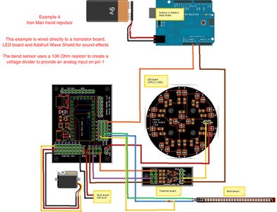


The bend sensor in this example is used as a trigger- once its output value reaches a certain level it causes the Arduino to run the specified code. You can change the threshold value to alter the point at which the sensor acts as a trigger. If you open the Arduino serial monitor window while the servo board is connected to your computer you can see when the bend sensor triggers. The bend sensor is set up using a voltage divider to provide an analog input value on input pin 1.
This example uses the Adafruit Wave Shield to provide sound effects. The instructions for building and setting up the Wave Shield can be found on the Wave Shield web page at http://www.ladyada.net/make/waveshield/
There are several code examples on the Wave Shield page for playing back audio files. The example I used is the play6_hc.pde example located at http://www.ladyada.net/make/waveshield/libraryhcplay6.html
Just download the sound file to a SD memory card and place it in your Wave Shield and you're good to go.
For the wiring schematic I did it two ways. The first version uses a small surface mount transistor board to activate the LED board and the Wave Shield. The second version uses two TIP 120 transistors instead- they are functionally identical. The big difference is the TIP 120 transistors can handle much larger current loads than the small surface mount transistors- but the TIP 120s take up a lot more space.
The transistors are needed because the Wave Shield needs a switch to tell it when to play the audio file (the transistor grounds the Wave Shield input pin when activated) and multiple LEDs use far more current than a single Arduino output pin can provide.
When the bend sensor is bent far enough the LEDs will fade, the sound file will play and then a servo will move. The servo would be used to open a forearm missile compartment.
For more Iron Man costuming fun check out the SIWDAT site-
http://www.siwdat.com/index.html
Copy and paste this sketch into your Arduino window-
/*
* Example 4
* Bend Sensor/Wave shield
* This example uses a bend sensor as a trigger to fade a LED with sound effect
* using a Wave shield and then activate a servo
* Honus 2010
* Modified from Knock Sensor code created 25 Mar 2007 by David Cuartielles
* and modified 4 Sep 2010 by Tom Igoe
*/
#include "Servo.h" // include the servo library
Servo servo1; // creates an instance of the servo object to control a servo
// these constants won't change:
const int servoPin1 = 9; // control pin for servo
const int triggerSensor = 1; // the sensor is connected to analog pin 1
const int threshold = 400; // threshold value to decide when the sensor input triggers
const int ledPin = 11;
int soundPin1 = 10; // control pin for sound board
// these variables will change:
int sensorReading = 0; // variable to store the value read from the sensor pin
int ledState = LOW; // variable used to store the last LED status, to toggle the light
void setup() {
Serial.begin(9600); // use the serial port
servo1.attach(servoPin1); // attaches the servo on pin 9 to the servo object
pinMode(soundPin1, OUTPUT); // sets the sound pin as output
digitalWrite(soundPin1, LOW);
}
void loop() {
servo1.write(20); // move the servo to 20 degree position
// read the sensor and store it in the variable sensorReading:
sensorReading = analogRead(triggerSensor);
// if the sensor reading is greater than the threshold:
if (sensorReading >= threshold) {
digitalWrite(soundPin1, HIGH); // turn the sound on
delay(10); // wait ten milliseconds
digitalWrite(soundPin1, LOW); // turn the sound off
// fade in from min to max in increments of 5 points:
for(int fadeValue = 0 ; fadeValue <= 255; fadeValue +=5) {
// sets the value (range from 0 to 255):
analogWrite(ledPin, fadeValue);
// wait for 30 milliseconds to see the dimming effect
delay(40);
}
// fade out from max to min in increments of 5 points:
for(int fadeValue = 255 ; fadeValue >= 0; fadeValue -=5) {
// sets the value (range from 0 to 255):
analogWrite(ledPin, fadeValue);
// wait for 30 milliseconds to see the dimming effect
delay(40);
// send the string "trigger!" back to the computer, followed by newline
Serial.println("trigger!");
}
servo1.write(160); // move the servo to 160 degree position
delay(3000); // wait 3 seconds
servo1.write(20); // move the servo to 20 degree position
}
delay (3000); // three second delay to avoid overloading the serial port buffer
}
Attachments
Step 9: Controlling Servos


Example 5- controlling a servo using analog input
These two examples show how easy it is to control servos using an analog input. You can use any analog input device you want- I'll use a 10k Ohm potentiometer for the example wiring diagram. As you turn the pot (and change its value) the servo moves proportionally.
The second code example simply extends the first example to control six servos from six inputs. This kind of control comes in really handy if you want to control several servos using bend sensors attached to a glove. This would work really well for controlling an animatronic mask.
/*
* Example 5
* Servo Control
* This example uses a servos and analog input to move the servo according to the sensor input value
* Honus 2010
*/
#include "Servo.h" // include the servo library
Servo servo1; // creates an instance of the servo object to control a servo
int analogPin = 0; // the analog pin that the sensor is on
int analogValue = 0; // the value returned from the analog sensor
int servoPin = 4; // Control pin for servo motor
void setup() {
servo1.attach(servoPin); // attaches the servo on pin 9 to the servo object
}
void loop()
{
analogValue = analogRead(analogPin); // read the analog input (value between 0 and 1023)
analogValue = map(analogValue, 0, 1023, 0, 179); // map the analog value (0 - 1023) to the angle of the servo (0 - 179)
servo1.write(analogValue); // write the new mapped analog value to set the position of the servo
delay(15); // waits for the servo to get there
}
Example 5a- Controlling 6 servos using multiple inputs
/*
* Example 5a
* Servo Control6
* This example uses 6 servos and analog inputs to move the servos according to the sensor input values
* Honus 2010
*/
#include // include the servo library
Servo servoMotor1; // creates an instance of the servo object to control a servo
Servo servoMotor2;
Servo servoMotor3;
Servo servoMotor4;
Servo servoMotor5;
Servo servoMotor6;
int analogPin1 = 0; // the analog pin that the sensor is on
int analogPin2 = 1;
int analogPin3 = 2;
int analogPin4 = 3;
int analogPin5 = 4;
int analogPin6 = 5;
int analogValue1 = 0; // the value returned from the analog sensor
int analogValue2 = 0;
int analogValue3 = 0;
int analogValue4 = 0;
int analogValue5 = 0;
int analogValue6 = 0;
int servoPin1 = 4; // Control pin for servo motor
int servoPin2 = 5;
int servoPin3 = 6;
int servoPin4 = 7;
int servoPin5 = 8;
int servoPin6 = 9;
void setup() {
servoMotor1.attach(servoPin1); // attaches the servo on pin 4 to the servo object
servoMotor2.attach(servoPin2); // attaches the servo on pin 5 to the servo object
servoMotor3.attach(servoPin3); // attaches the servo on pin 6 to the servo object
servoMotor4.attach(servoPin4); // attaches the servo on pin 7 to the servo object
servoMotor5.attach(servoPin5); // attaches the servo on pin 8 to the servo object
servoMotor6.attach(servoPin6); // attaches the servo on pin 9 to the servo object
}
void loop()
{
analogValue1 = analogRead(analogPin1); // read the analog input (value between 0 and 1023)
analogValue1 = map(analogValue1, 0, 1023, 0, 179); // map the analog value (0 - 1023) to the angle of the servo (0 - 179)
servoMotor1.write(analogValue1); // write the new mapped analog value to set the position of the servo
analogValue2 = analogRead(analogPin2);
analogValue2 = map(analogValue2, 0, 1023, 0, 179);
servoMotor2.write(analogValue2);
analogValue3 = analogRead(analogPin3);
analogValue3 = map(analogValue3, 0, 1023, 0, 179);
servoMotor3.write(analogValue3);
analogValue4 = analogRead(analogPin4);
analogValue4 = map(analogValue4, 0, 1023, 0, 179);
servoMotor4.write(analogValue4);
analogValue5 = analogRead(analogPin5);
analogValue5 = map(analogValue5, 0, 1023, 0, 179);
servoMotor5.write(analogValue5);
analogValue6 = analogRead(analogPin6);
analogValue6 = map(analogValue6, 0, 1023, 0, 179);
servoMotor6.write(analogValue6);
delay(15); // waits for the servo to get there
}
Step 10: Nunchuck Control


Example 6- Using a Wii nunchuck as an input device
I wrote this bit of code back in 2007 to use a Wii nunchuck as an input device for an animatronic Predator cannon (see example 7.) The Wii nunchuck communicates to an Arduino over four wires (power, ground, data and clock) using an I²C interface (Inter-Integrated Circuit aka two-wire interface or TWI.)
The Wii nunchuck has a three axis accelerometer, joystick and two push buttons- for $20 it's an awesome input device for Arduino projects. The code presented here is a further modification of the code by Tod Kurt that was presented in his Bionic Arduino class- I simply extended it to control everything but the accelerometer Z axis, which I found I rarely used.
Using this code you can control four servos using the accelerometer and joystick functions and use the two push buttons to turn on LEDs (or transistors or even run a bit of code.)
/*
* Example 6
* Nunchuck control for four servos and two button inputs
* Honus 2007
* This allows the use of a Wii nunchuck as an input device and is modified/extended from the original code
* by Tod E. Kurt and Windmeadow Labs
*2007 Tod E. Kurt, http://todbot.com/blog/
*The Wii Nunchuck reading code is taken from Windmeadow Labs, http://www.windmeadow.com/node/42
*/
#include "Wire.h"
int ledPin1 = 13; // Control pin for LED 1
int ledPin2 = 12; // Control pin for LED 2
int servoPin1 = 9; // Control pin for servo motor
int servoPin2 = 8; // Control pin for servo motor
int servoPin3 = 7; // Control pin for servo motor
int servoPin4 = 6; // Control pin for servo motor
int pulseWidth1 = 0; // Amount to pulse the servo 1
int pulseWidth2 = 0; // Amount to pulse the servo 2
int pulseWidth3 = 0; // Amount to pulse the servo 3
int pulseWidth4 = 0; // Amount to pulse the servo 4
int refreshTime = 20; // the time in millisecs needed in between pulses
long lastPulse1;
long lastPulse2;
long lastPulse3;
long lastPulse4;
int minPulse = 700; // minimum pulse width
int loop_cnt=0;
void setup()
{
Serial.begin(19200);
pinMode(servoPin1, OUTPUT); // Set servo pin as an output pin
pinMode(servoPin2, OUTPUT); // Set servo pin as an output pin
pinMode(servoPin3, OUTPUT); // Set servo pin as an output pin
pinMode(servoPin4, OUTPUT); // Set servo pin as an output pin
pulseWidth1 = minPulse; // Set the motor position to the minimum
pulseWidth2 = minPulse; // Set the motor position to the minimum
pulseWidth3 = minPulse; // Set the motor position to the minimum
pulseWidth4 = minPulse; // Set the motor position to the minimum
nunchuck_init(); // send the initilization handshake
Serial.print("NunchuckServo ready\n");
}
void loop()
{
checkNunchuck1();
updateServo1(); // update servo 1 position
checkNunchuck2();
updateServo2(); // update servo 2 position
checkNunchuck3();
updateServo3(); // update servo 3 position
checkNunchuck4();
updateServo4(); // update servo 4 position
if( nunchuck_zbutton() ) // light the LED if z button is pressed
digitalWrite(ledPin1, HIGH);
else
digitalWrite(ledPin1,LOW);
if( nunchuck_cbutton() ) // light the LED if c button is pressed
digitalWrite(ledPin2, HIGH);
else
digitalWrite(ledPin2,LOW);
delay(1); // this is here to give a known time per loop
}
void checkNunchuck1()
{
if( loop_cnt > 100 ) { // loop()s is every 1msec, this is every 100msec
nunchuck_get_data();
nunchuck_print_data();
float tilt = nunchuck_accelx(); // x-axis, in this case ranges from ~70 - ~185
tilt = (tilt - 70) * 1.5; // convert to angle in degrees, roughly
pulseWidth1 = (tilt * 9) + minPulse; // convert angle to microseconds
loop_cnt = 0; // reset for
}
loop_cnt++;
}
// called every loop().
// uses global variables servoPin, pulsewidth, lastPulse, & refreshTime
void updateServo1()
{
// pulse the servo again if rhe refresh time (20 ms) have passed:
if (millis() - lastPulse1 >= refreshTime) {
digitalWrite(servoPin1, HIGH); // Turn the motor on
delayMicroseconds(pulseWidth1); // Length of the pulse sets the motor position
digitalWrite(servoPin1, LOW); // Turn the motor off
lastPulse1 = millis(); // save the time of the last pulse
}
}
void checkNunchuck2()
{
if( loop_cnt > 100 ) { // loop()s is every 1msec, this is every 100msec
nunchuck_get_data();
nunchuck_print_data();
float tilt = nunchuck_accely(); // y-axis, in this case ranges from ~70 - ~185
tilt = (tilt - 70) * 1.5; // convert to angle in degrees, roughly
pulseWidth2 = (tilt * 9) + minPulse; // convert angle to microseconds
loop_cnt = 0; // reset for
}
loop_cnt++;
}
// called every loop().
// uses global variables servoPin, pulsewidth, lastPulse, & refreshTime
void updateServo2()
{
// pulse the servo again if rhe refresh time (20 ms) have passed:
if (millis() - lastPulse2 >= refreshTime) {
digitalWrite(servoPin2, HIGH); // Turn the motor on
delayMicroseconds(pulseWidth2); // Length of the pulse sets the motor position
digitalWrite(servoPin2, LOW); // Turn the motor off
lastPulse2 = millis(); // save the time of the last pulse
}
}
void checkNunchuck3()
{
if( loop_cnt > 100 ) { // loop()s is every 1msec, this is every 100msec
nunchuck_get_data();
nunchuck_print_data();
float tilt = nunchuck_joyx(); // x-axis, in this case ranges from ~70 - ~185
tilt = (tilt - 70) * 1.5; // convert to angle in degrees, roughly
pulseWidth3 = (tilt * 9) + minPulse; // convert angle to microseconds
loop_cnt = 0; // reset for
}
loop_cnt++;
}
// called every loop().
// uses global variables servoPin, pulsewidth, lastPulse, & refreshTime
void updateServo3()
{
// pulse the servo again if rhe refresh time (20 ms) have passed:
if (millis() - lastPulse3 >= refreshTime) {
digitalWrite(servoPin3, HIGH); // Turn the motor on
delayMicroseconds(pulseWidth3); // Length of the pulse sets the motor position
digitalWrite(servoPin3, LOW); // Turn the motor off
lastPulse3 = millis(); // save the time of the last pulse
}
}
void checkNunchuck4()
{
if( loop_cnt > 100 ) { // loop()s is every 1msec, this is every 100msec
nunchuck_get_data();
nunchuck_print_data();
float tilt = nunchuck_joyy(); // y-axis, in this case ranges from ~70 - ~185
tilt = (tilt - 70) * 1.5; // convert to angle in degrees, roughly
pulseWidth4 = (tilt * 9) + minPulse; // convert angle to microseconds
loop_cnt = 0; // reset for
}
loop_cnt++;
}
// called every loop().
// uses global variables servoPin, pulsewidth, lastPulse, & refreshTime
void updateServo4()
{
// pulse the servo again if rhe refresh time (20 ms) have passed:
if (millis() - lastPulse4 >= refreshTime) {
digitalWrite(servoPin4, HIGH); // Turn the motor on
delayMicroseconds(pulseWidth4); // Length of the pulse sets the motor position
digitalWrite(servoPin4, LOW); // Turn the motor off
lastPulse4 = millis(); // save the time of the last pulse
}
}
//
// Nunchuck functions
//
static uint8_t nunchuck_buf[6]; // array to store nunchuck data,
// initialize the I2C system, join the I2C bus,
// and tell the nunchuck we're talking to it
void nunchuck_init()
{
Wire.begin(); // join i2c bus as master
Wire.beginTransmission(0x52); // transmit to device 0x52
Wire.send(0x40); // sends memory address
Wire.send(0x00); // sends sent a zero.
Wire.endTransmission(); // stop transmitting
}
// Send a request for data to the nunchuck
// was "send_zero()"
void nunchuck_send_request()
{
Wire.beginTransmission(0x52); // transmit to device 0x52
Wire.send(0x00); // sends one byte
Wire.endTransmission(); // stop transmitting
}
// Receive data back from the nunchuck,
// returns 1 on successful read. returns 0 on failure
int nunchuck_get_data()
{
int cnt=0;
Wire.requestFrom (0x52, 6); // request data from nunchuck
while (Wire.available ()) {
// receive byte as an integer
nunchuck_buf[cnt] = nunchuk_decode_byte(Wire.receive());
cnt++;
}
nunchuck_send_request(); // send request for next data payload
// If we recieved the 6 bytes, then go print them
if (cnt >= 5) {
return 1; // success
}
return 0; //failure
}
// Print the input data we have recieved
// accel data is 10 bits long
// so we read 8 bits, then we have to add
// on the last 2 bits. That is why I
// multiply them by 2 * 2
void nunchuck_print_data()
{
static int i=0;
int joy_x_axis = nunchuck_buf[0];
int joy_y_axis = nunchuck_buf[1];
int accel_x_axis = nunchuck_buf[2]; // * 2 * 2;
int accel_y_axis = nunchuck_buf[3]; // * 2 * 2;
int accel_z_axis = nunchuck_buf[4]; // * 2 * 2;
int z_button = 0;
int c_button = 0;
// byte nunchuck_buf[5] contains bits for z and c buttons
// it also contains the least significant bits for the accelerometer data
// so we have to check each bit of byte outbuf[5]
if ((nunchuck_buf[5] >> 0) & 1)
z_button = 1;
if ((nunchuck_buf[5] >> 1) & 1)
c_button = 1;
if ((nunchuck_buf[5] >> 2) & 1)
accel_x_axis += 2;
if ((nunchuck_buf[5] >> 3) & 1)
accel_x_axis += 1;
if ((nunchuck_buf[5] >> 4) & 1)
accel_y_axis += 2;
if ((nunchuck_buf[5] >> 5) & 1)
accel_y_axis += 1;
if ((nunchuck_buf[5] >> 6) & 1)
accel_z_axis += 2;
if ((nunchuck_buf[5] >> 7) & 1)
accel_z_axis += 1;
Serial.print(i,DEC);
Serial.print("\t");
Serial.print("joy:");
Serial.print(joy_x_axis,DEC);
Serial.print(",");
Serial.print(joy_y_axis, DEC);
Serial.print(" \t");
Serial.print("acc:");
Serial.print(accel_x_axis, DEC);
Serial.print(",");
Serial.print(accel_y_axis, DEC);
Serial.print(",");
Serial.print(accel_z_axis, DEC);
Serial.print("\t");
Serial.print("but:");
Serial.print(z_button, DEC);
Serial.print(",");
Serial.print(c_button, DEC);
Serial.print("\r\n"); // newline
i++;
}
// Encode data to format that most wiimote drivers except
// only needed if you use one of the regular wiimote drivers
char nunchuk_decode_byte (char x)
{
x = (x ^ 0x17) + 0x17;
return x;
}
// returns zbutton state: 1=pressed, 0=notpressed
int nunchuck_zbutton()
{
return ((nunchuck_buf[5] >> 0) & 1) ? 0 : 1; // voodoo
}
// returns zbutton state: 1=pressed, 0=notpressed
int nunchuck_cbutton()
{
return ((nunchuck_buf[5] >> 1) & 1) ? 0 : 1; // voodoo
}
// returns value of x-axis joystick
int nunchuck_joyx()
{
return nunchuck_buf[0];
}
// returns value of y-axis joystick
int nunchuck_joyy()
{
return nunchuck_buf[1];
}
// returns value of x-axis accelerometer
int nunchuck_accelx()
{
return nunchuck_buf[2]; // FIXME: this leaves out 2-bits of the data
}
// returns value of y-axis accelerometer
int nunchuck_accely()
{
return nunchuck_buf[3]; // FIXME: this leaves out 2-bits of the data
}
// returns value of z-axis accelerometer
int nunchuck_accelz()
{
return nunchuck_buf[4]; // FIXME: this leaves out 2-bits of the data
}
Step 11: Predator Cannon


Using a modified Wii nunchuck board we can make a "head tracking" system to control an animatronic Predator cannon. This system was designed to look like the cannon mechanism in the first Predator movie.
The nunchuck board is removed from its case, the joystick is removed and the board is placed level in the top of the Predator Bio helmet. The wires are extended for the buttons so they can be used as fingertip buttons to activate the cannon and trigger the firing sequence.
To remove the circuit board from the Wii nunchuck case you'll need a tri-wing screwdriver-
http://www.play-asia.com/paOS-13-71-1e-49-en-70-1fe.html
The sound effect is handled just like the Iron Man repulsor in example 4 using the Adafruit Wave Shield. Since the Wave Shield code used can support six individual sounds you can add five other Predator sounds and activate them using fingertip switches- neat!
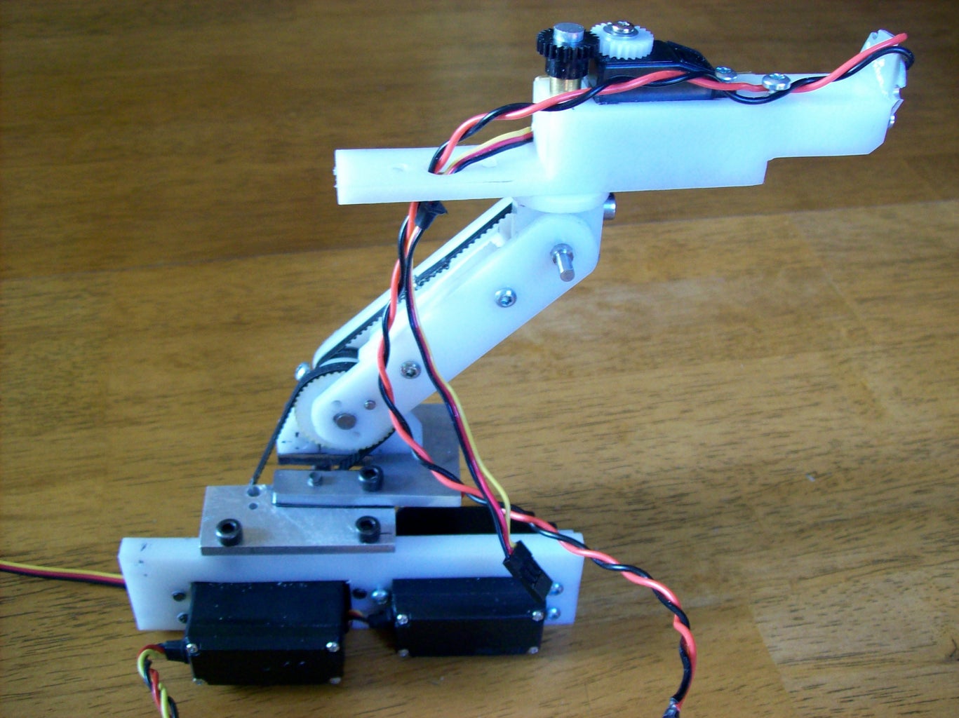
There is one servo that is geared 4:1 that raises the cannon arm- in the code you can see this as the servo rotating 180 degrees, thereby raising the cannon arm 45 degrees. The other two servos aim the cannon using the accelerometer inputs. There are transistors that turn on the aiming servos and laser sight when one button is pressed. If the aiming servos were always on then the cannon would rotate even when it was in the lowered position, so they need a way of being turned off when the cannon is lowered.
So push one one button and the cannon raises up, the aiming servos turn on and the laser sight turns on. Push the second button and the cannon fires- two transistors turn on the cannon LED and activate the firing sound. Three red LEDs can be used in place of the laser sight. The cannon LED can be anything from several small LEDs to a high power Luxeon LED. When using a high power Luxeon LED be sure to use a constant current driver to power it.
Servos can draw a fair bit of power so I use a TIP 120 transistor to turn on the aiming servos.
The prototype cannon mechanism was built using Delrin plastic scraps and timing belts and gears from old desktop printers and photocopiers I found in the trash. When I build the final version for the Predator costume it will probably be entirely gear driven to make it more compact and cleaner.
For Predator costuming info check out http://www.thehunterslair.com
Those individuals interested in obtaining a resin cannon casting should contact my friend Carl here- http://www.accurizedhunterparts.com/
Carl's work is absolutely brilliant- check out the photos below of the Predator backpack clay sculpt that he created for this project. That's a lot of clay! When contacting Carl please be patient as he's extremely busy and he has a large backlog of work.
Here's the code-
/*
* Example 7
* Predator Cannon
* This uses a modified Wii nunchuck as a head tracking input device to control an animatronic Predator cannon
* Adafruit Wave shield is used for sound effects
* Honus 2007, updated 2010
* Wii nunchuck reading code modified/extended from nunchuck code by Tod E. Kurt and Windmeadow Labs
* 2007 Tod E. Kurt, http://todbot.com/blog/
* The Wii Nunchuck reading code is taken from Windmeadow Labs, http://www.windmeadow.com/node/42
*/
#include "Wire.h" // include the Wire library
#include "Servo.h" // include the servo library
Servo servo3; // creates an instance of the servo object to control a servo
int controlPin1 = 6; // Control pin for sound effects board using z button
int transistorPin1 = 13; // Control pin for LED using z button
int transistorPin2 = 12; // Control pin for laser sight using c button
int transistorPin3 = 11; // Control pin for servo 1 using c button
int transistorPin4 = 10; // Control pin for servo 2 using c button
int servoPin1 = 7; // Control pin for servo 1 using accelerometer x axis
int servoPin2 = 8; // Control pin for servo 2 using accelerometer y axis
int servoPin3 = 9; // control pin for arm servo
int pulseWidth1 = 0; // Amount to pulse the servo 1
int pulseWidth2 = 0; // Amount to pulse the servo 2
int refreshTime = 20; // the time in millisecs needed in between servo pulses
long lastPulse1;
long lastPulse2;
int minPulse = 700; // minimum servo pulse width
int loop_cnt=0;
boolean button_down = false;
unsigned long start;
void setup()
{
Serial.begin(19200);
servo3.attach(servoPin3); // attaches the servo on pin 9 to the servo object
pinMode(controlPin1, OUTPUT); // Set control pin 1 as output
pinMode(transistorPin1, OUTPUT); // Set transistor pin 1 as output
pinMode(transistorPin2, OUTPUT); // Set transistor pin 2 as output
pinMode(transistorPin3, OUTPUT); // Set transistor pin 3 as output
pinMode(transistorPin4, OUTPUT); // Set transistor pin 4 as output
pinMode(servoPin1, OUTPUT); // Set servo pin 1 as output
pinMode(servoPin2, OUTPUT); // Set servo pin 2 as output
pulseWidth1 = minPulse; // Set the servo position to the minimum
pulseWidth2 = minPulse; // Set the servo position to the minimum
nunchuck_init(); // send the initilization handshake
Serial.print("NunchuckServo ready\n");
}
void loop()
{
checkNunchuck1();
updateServo1(); // update servo 1 position
checkNunchuck2();
updateServo2(); // update servo 2 position
if( nunchuck_cbutton() ) {
digitalWrite(transistorPin2, HIGH); // turn on transistor pin 2 if c button is pressed
digitalWrite(transistorPin3, HIGH); // turn on transistor pin 3 if c button is pressed
digitalWrite(transistorPin4, HIGH); // turn on transistor pin 4 if c button is pressed
servo3.write(180);
}
else {
digitalWrite(transistorPin2, LOW);
digitalWrite(transistorPin3, LOW);
digitalWrite(transistorPin4, LOW);
servo3.write(0);
}
if ( nunchuck_zbutton() )
{
if (!button_down) // if button was just pressed do this
{
digitalWrite(controlPin1, HIGH);
button_down = true;
start = millis();
}
else if (millis() - start > 1200) // if timer has elapsed do this
{
digitalWrite(transistorPin1, HIGH);
}
}
else // if button is up do this
{
button_down = false;
digitalWrite(controlPin1, LOW);
digitalWrite(transistorPin1, LOW);
}
delay(1); // this is here to give a known time per loop
}
void checkNunchuck1()
{
if( loop_cnt > 100 ) { // loop()s is every 1msec, this is every 100msec
nunchuck_get_data();
nunchuck_print_data();
float tilt = nunchuck_accelx(); // x-axis, in this case ranges from ~70 - ~185
tilt = (tilt - 70) * 1.5; // convert to angle in degrees, roughly
pulseWidth1 = (tilt * 9) + minPulse; // convert angle to microseconds
loop_cnt = 0; // reset for
}
loop_cnt++;
}
// called every loop().
// uses global variables servoPin, pulsewidth, lastPulse, & refreshTime
void updateServo1()
{
// pulse the servo again if rhe refresh time (20 ms) have passed:
if (millis() - lastPulse1 >= refreshTime) {
digitalWrite(servoPin1, HIGH); // Turn the servo on
delayMicroseconds(pulseWidth1); // Length of the pulse sets the servo position
digitalWrite(servoPin1, LOW); // Turn the servo off
lastPulse1 = millis(); // save the time of the last pulse
}
}
void checkNunchuck2()
{
if( loop_cnt > 100 ) { // loop()s is every 1msec, this is every 100msec
nunchuck_get_data();
nunchuck_print_data();
float tilt = nunchuck_accely(); // y-axis, in this case ranges from ~70 - ~185
tilt = (tilt - 70) * 1.5; // convert to angle in degrees, roughly
pulseWidth2 = (tilt * 9) + minPulse; // convert angle to microseconds
loop_cnt = 0; // reset for
}
loop_cnt++;
}
// called every loop().
// uses global variables servoPin, pulsewidth, lastPulse, & refreshTime
void updateServo2()
{
// pulse the servo again if rhe refresh time (20 ms) have passed:
if (millis() - lastPulse2 >= refreshTime) {
digitalWrite(servoPin2, HIGH); // Turn the servo on
delayMicroseconds(pulseWidth2); // Length of the pulse sets the servo position
digitalWrite(servoPin2, LOW); // Turn the servo off
lastPulse2 = millis(); // save the time of the last pulse
}
}
//
// Nunchuck functions
//
static uint8_t nunchuck_buf[6]; // array to store nunchuck data,
// initialize the I2C system, join the I2C bus,
// and tell the nunchuck we're talking to it
void nunchuck_init()
{
Wire.begin(); // join i2c bus as master
Wire.beginTransmission(0x52); // transmit to device 0x52
Wire.send(0x40); // sends memory address
Wire.send(0x00); // sends sent a zero.
Wire.endTransmission(); // stop transmitting
}
// Send a request for data to the nunchuck
// was "send_zero()"
void nunchuck_send_request()
{
Wire.beginTransmission(0x52); // transmit to device 0x52
Wire.send(0x00); // sends one byte
Wire.endTransmission(); // stop transmitting
}
// Receive data back from the nunchuck,
// returns 1 on successful read. returns 0 on failure
int nunchuck_get_data()
{
int cnt=0;
Wire.requestFrom (0x52, 6); // request data from nunchuck
while (Wire.available ()) {
// receive byte as an integer
nunchuck_buf[cnt] = nunchuk_decode_byte(Wire.receive());
cnt++;
}
nunchuck_send_request(); // send request for next data payload
// If we recieved the 6 bytes, then go print them
if (cnt >= 5) {
return 1; // success
}
return 0; //failure
}
// Print the input data we have recieved
// accel data is 10 bits long
// so we read 8 bits, then we have to add
// on the last 2 bits. That is why I
// multiply them by 2 * 2
void nunchuck_print_data()
{
static int i=0;
int joy_x_axis = nunchuck_buf[0];
int joy_y_axis = nunchuck_buf[1];
int accel_x_axis = nunchuck_buf[2]; // * 2 * 2;
int accel_y_axis = nunchuck_buf[3]; // * 2 * 2;
int accel_z_axis = nunchuck_buf[4]; // * 2 * 2;
int z_button = 0;
int c_button = 0;
// byte nunchuck_buf[5] contains bits for z and c buttons
// it also contains the least significant bits for the accelerometer data
// so we have to check each bit of byte outbuf[5]
if ((nunchuck_buf[5] >> 0) & 1)
z_button = 1;
if ((nunchuck_buf[5] >> 1) & 1)
c_button = 1;
if ((nunchuck_buf[5] >> 2) & 1)
accel_x_axis += 2;
if ((nunchuck_buf[5] >> 3) & 1)
accel_x_axis += 1;
if ((nunchuck_buf[5] >> 4) & 1)
accel_y_axis += 2;
if ((nunchuck_buf[5] >> 5) & 1)
accel_y_axis += 1;
if ((nunchuck_buf[5] >> 6) & 1)
accel_z_axis += 2;
if ((nunchuck_buf[5] >> 7) & 1)
accel_z_axis += 1;
Serial.print(i,DEC);
Serial.print("\t");
Serial.print("joy:");
Serial.print(joy_x_axis,DEC);
Serial.print(",");
Serial.print(joy_y_axis, DEC);
Serial.print(" \t");
Serial.print("acc:");
Serial.print(accel_x_axis, DEC);
Serial.print(",");
Serial.print(accel_y_axis, DEC);
Serial.print(",");
Serial.print(accel_z_axis, DEC);
Serial.print("\t");
Serial.print("but:");
Serial.print(z_button, DEC);
Serial.print(",");
Serial.print(c_button, DEC);
Serial.print("\r\n"); // newline
i++;
}
// Encode data to format that most wiimote drivers except
// only needed if you use one of the regular wiimote drivers
char nunchuk_decode_byte (char x)
{
x = (x ^ 0x17) + 0x17;
return x;
}
// returns zbutton state: 1=pressed, 0=notpressed
int nunchuck_zbutton()
{
return ((nunchuck_buf[5] >> 0) & 1) ? 0 : 1; // voodoo
}
// returns zbutton state: 1=pressed, 0=notpressed
int nunchuck_cbutton()
{
return ((nunchuck_buf[5] >> 1) & 1) ? 0 : 1; // voodoo
}
// returns value of x-axis joystick
int nunchuck_joyx()
{
return nunchuck_buf[0];
}
// returns value of y-axis joystick
int nunchuck_joyy()
{
return nunchuck_buf[1];
}
// returns value of x-axis accelerometer
int nunchuck_accelx()
{
return nunchuck_buf[2]; // FIXME: this leaves out 2-bits of the data
}
// returns value of y-axis accelerometer
int nunchuck_accely()
{
return nunchuck_buf[3]; // FIXME: this leaves out 2-bits of the data
}
// returns value of z-axis accelerometer
int nunchuck_accelz()
{
return nunchuck_buf[4]; // FIXME: this leaves out 2-bits of the data
}
Attachments
Step 12: War Machine Cannon

Example 8- War Machine cannon
You want to be the War Machine? This example is based on the Predator cannon but uses a motor connected to a transistor to spin the cannon barrels. When you push the fire button the motor turns on. There is a 1N4004 diode to prevent back voltage from the motor damaging the controller output pin.
A War Machine cannon is substantially larger than a Predator cannon and would require larger, more powerful servos so I have individual TIP 120 transistors shown on the wiring diagram.
For mounting the cannon Servocity sells pan/tilt mechanisms that would be perfect for this application-
http://www.servocity.com/html/spt200_pan___tilt_system.html
/*
* Example 8
* Iron Man War Machine Cannon
* This uses a modified Wii nunchuck as a head tracking input device to control an animatronic Iron Man War Machine cannon
* Adafruit Wave shield is used for sound effects
* Honus 2010
* Wii nunchuck reading code modified/extended from nunchuck code by Tod E. Kurt and Windmeadow Labs
* 2007 Tod E. Kurt, http://todbot.com/blog/
* The Wii Nunchuck reading code is taken from Windmeadow Labs, http://www.windmeadow.com/node/42
*/
#include "Wire.h" // include the Wire library
int controlPin1 = 7; // Control pin for sound effects board using z button
int transistorPin1 = 13; // Control pin for cannon LED using z button
int transistorPin2 = 12; // Control pin for servo 1 using c button
int transistorPin3 = 11; // Control pin for servo 2 using c button
int transistorPin4 = 10; // Control pin for cannon motor using z button
int servoPin1 = 9; // Control pin for servo 1 using accelerometer x axis
int servoPin2 = 8; // Control pin for servo 2 using accelerometer y axis
int pulseWidth1 = 0; // Amount to pulse the servo 1
int pulseWidth2 = 0; // Amount to pulse the servo 2
int refreshTime = 20; // the time in millisecs needed in between servo pulses
long lastPulse1;
long lastPulse2;
int minPulse = 700; // minimum servo pulse width
int loop_cnt=0;
boolean button_down = false;
unsigned long start;
void setup()
{
Serial.begin(19200);
pinMode(controlPin1, OUTPUT); // Set control pin 1 as output
pinMode(transistorPin1, OUTPUT); // Set transistor pin 1 as output
pinMode(transistorPin2, OUTPUT); // Set transistor pin 2 as output
pinMode(transistorPin3, OUTPUT); // Set transistor pin 3 as output
pinMode(transistorPin4, OUTPUT); // Set transistor pin 4 as output
pinMode(servoPin1, OUTPUT); // Set servo pin 1 as output
pinMode(servoPin2, OUTPUT); // Set servo pin 2 as output
pulseWidth1 = minPulse; // Set the servo position to the minimum
pulseWidth2 = minPulse; // Set the servo position to the minimum
nunchuck_init(); // send the initilization handshake
Serial.print("NunchuckServo ready\n");
}
void loop()
{
checkNunchuck1();
updateServo1(); // update servo 1 position
checkNunchuck2();
updateServo2(); // update servo 2 position
if( nunchuck_cbutton() ) {
digitalWrite(transistorPin2, HIGH); // turn on transistor pin 2 if c button is pressed
digitalWrite(transistorPin3, HIGH); // turn on transistor pin 3 if c button is pressed
}
else {
digitalWrite(transistorPin2, LOW); // turn off transistor pin 2
digitalWrite(transistorPin3, LOW);
}
if ( nunchuck_zbutton() )
{
if (!button_down) // if button was just pressed do this
{
digitalWrite(controlPin1, HIGH); // turn on sound effect
button_down = true;
start = millis();
}
else if (millis() - start > 1200) // if timer has elapsed do this
{
digitalWrite(transistorPin1, HIGH); // turn on cannon LED
digitalWrite(transistorPin4, HIGH); // turn on cannon motor
}
}
else // if button is up do this
{
button_down = false;
digitalWrite(controlPin1, LOW); // turn off sound effect
digitalWrite(transistorPin1, LOW); // turn off cannon LED
digitalWrite(transistorPin4, LOW); // turn off cannon motor
}
delay(1); // this is here to give a known time per loop
}
void checkNunchuck1()
{
if( loop_cnt > 100 ) { // loop()s is every 1msec, this is every 100msec
nunchuck_get_data();
nunchuck_print_data();
float tilt = nunchuck_accelx(); // x-axis, in this case ranges from ~70 - ~185
tilt = (tilt - 70) * 1.5; // convert to angle in degrees, roughly
pulseWidth1 = (tilt * 9) + minPulse; // convert angle to microseconds
loop_cnt = 0; // reset for
}
loop_cnt++;
}
// called every loop().
// uses global variables servoPin, pulsewidth, lastPulse, & refreshTime
void updateServo1()
{
// pulse the servo again if rhe refresh time (20 ms) have passed:
if (millis() - lastPulse1 >= refreshTime) {
digitalWrite(servoPin1, HIGH); // Turn the servo on
delayMicroseconds(pulseWidth1); // Length of the pulse sets the servo position
digitalWrite(servoPin1, LOW); // Turn the servo off
lastPulse1 = millis(); // save the time of the last pulse
}
}
void checkNunchuck2()
{
if( loop_cnt > 100 ) { // loop()s is every 1msec, this is every 100msec
nunchuck_get_data();
nunchuck_print_data();
float tilt = nunchuck_accely(); // y-axis, in this case ranges from ~70 - ~185
tilt = (tilt - 70) * 1.5; // convert to angle in degrees, roughly
pulseWidth2 = (tilt * 9) + minPulse; // convert angle to microseconds
loop_cnt = 0; // reset for
}
loop_cnt++;
}
// called every loop().
// uses global variables servoPin, pulsewidth, lastPulse, & refreshTime
void updateServo2()
{
// pulse the servo again if rhe refresh time (20 ms) have passed:
if (millis() - lastPulse2 >= refreshTime) {
digitalWrite(servoPin2, HIGH); // Turn the servo on
delayMicroseconds(pulseWidth2); // Length of the pulse sets the servo position
digitalWrite(servoPin2, LOW); // Turn the servo off
lastPulse2 = millis(); // save the time of the last pulse
}
}
//
// Nunchuck functions
//
static uint8_t nunchuck_buf[6]; // array to store nunchuck data,
// initialize the I2C system, join the I2C bus,
// and tell the nunchuck we're talking to it
void nunchuck_init()
{
Wire.begin(); // join i2c bus as master
Wire.beginTransmission(0x52); // transmit to device 0x52
Wire.send(0x40); // sends memory address
Wire.send(0x00); // sends sent a zero.
Wire.endTransmission(); // stop transmitting
}
// Send a request for data to the nunchuck
// was "send_zero()"
void nunchuck_send_request()
{
Wire.beginTransmission(0x52); // transmit to device 0x52
Wire.send(0x00); // sends one byte
Wire.endTransmission(); // stop transmitting
}
// Receive data back from the nunchuck,
// returns 1 on successful read. returns 0 on failure
int nunchuck_get_data()
{
int cnt=0;
Wire.requestFrom (0x52, 6); // request data from nunchuck
while (Wire.available ()) {
// receive byte as an integer
nunchuck_buf[cnt] = nunchuk_decode_byte(Wire.receive());
cnt++;
}
nunchuck_send_request(); // send request for next data payload
// If we recieved the 6 bytes, then go print them
if (cnt >= 5) {
return 1; // success
}
return 0; //failure
}
// Print the input data we have recieved
// accel data is 10 bits long
// so we read 8 bits, then we have to add
// on the last 2 bits. That is why I
// multiply them by 2 * 2
void nunchuck_print_data()
{
static int i=0;
int joy_x_axis = nunchuck_buf[0];
int joy_y_axis = nunchuck_buf[1];
int accel_x_axis = nunchuck_buf[2]; // * 2 * 2;
int accel_y_axis = nunchuck_buf[3]; // * 2 * 2;
int accel_z_axis = nunchuck_buf[4]; // * 2 * 2;
int z_button = 0;
int c_button = 0;
// byte nunchuck_buf[5] contains bits for z and c buttons
// it also contains the least significant bits for the accelerometer data
// so we have to check each bit of byte outbuf[5]
if ((nunchuck_buf[5] >> 0) & 1)
z_button = 1;
if ((nunchuck_buf[5] >> 1) & 1)
c_button = 1;
if ((nunchuck_buf[5] >> 2) & 1)
accel_x_axis += 2;
if ((nunchuck_buf[5] >> 3) & 1)
accel_x_axis += 1;
if ((nunchuck_buf[5] >> 4) & 1)
accel_y_axis += 2;
if ((nunchuck_buf[5] >> 5) & 1)
accel_y_axis += 1;
if ((nunchuck_buf[5] >> 6) & 1)
accel_z_axis += 2;
if ((nunchuck_buf[5] >> 7) & 1)
accel_z_axis += 1;
Serial.print(i,DEC);
Serial.print("\t");
Serial.print("joy:");
Serial.print(joy_x_axis,DEC);
Serial.print(",");
Serial.print(joy_y_axis, DEC);
Serial.print(" \t");
Serial.print("acc:");
Serial.print(accel_x_axis, DEC);
Serial.print(",");
Serial.print(accel_y_axis, DEC);
Serial.print(",");
Serial.print(accel_z_axis, DEC);
Serial.print("\t");
Serial.print("but:");
Serial.print(z_button, DEC);
Serial.print(",");
Serial.print(c_button, DEC);
Serial.print("\r\n"); // newline
i++;
}
// Encode data to format that most wiimote drivers except
// only needed if you use one of the regular wiimote drivers
char nunchuk_decode_byte (char x)
{
x = (x ^ 0x17) + 0x17;
return x;
}
// returns zbutton state: 1=pressed, 0=notpressed
int nunchuck_zbutton()
{
return ((nunchuck_buf[5] >> 0) & 1) ? 0 : 1; // voodoo
}
// returns zbutton state: 1=pressed, 0=notpressed
int nunchuck_cbutton()
{
return ((nunchuck_buf[5] >> 1) & 1) ? 0 : 1; // voodoo
}
// returns value of x-axis joystick
int nunchuck_joyx()
{
return nunchuck_buf[0];
}
// returns value of y-axis joystick
int nunchuck_joyy()
{
return nunchuck_buf[1];
}
// returns value of x-axis accelerometer
int nunchuck_accelx()
{
return nunchuck_buf[2]; // FIXME: this leaves out 2-bits of the data
}
// returns value of y-axis accelerometer
int nunchuck_accely()
{
return nunchuck_buf[3]; // FIXME: this leaves out 2-bits of the data
}
// returns value of z-axis accelerometer
int nunchuck_accelz()
{
return nunchuck_buf[4]; // FIXME: this leaves out 2-bits of the data
}
Step 13: Going Wireless With XBee


Example 9- Wireless XBee radios
This allows you to use the Nunchuck control but does it by setting up one controller as a transmitter and another controller as the receiver. I use the Adafruit XBee wireless adapter because it's super easy to use and can work on both 3V and 5V so it's great for most any Arduino wireless project. The servo board is set up for point to point communication and the XBee adapter plugs directly into a socket at the top of the board. This setup would really well for controlling haunted house attractions.
You can get the XBee adapter and radios here-
http://www.adafruit.com/index.php?main_page=product_info&cPath=29&products_id=126
There is a complete XBee tutorial for building the XBee adapter and configuring it here-
http://www.ladyada.net/make/xbee/
Unlike the previous nuchuck control code, this code uses a new nunchuck library that cleans up the code considerably. It is called nunchuck_funcs.h
You can get it here-
http://todbot.com/blog/2008/02/18/wiichuck-wii-nunchuck-adapter-available/comment-page-3/
Simply place the nunchuck_funcs.h library into your Arduino libraries folder and you're good to go.
The wiring for this is exactly like the wiring for example 6 except the nunchuck is connected to the transmitter and the servos and LEDs are connected to the receiver.
Note- you cannot connect the USB to serial adapter while the XBee adapter is plugged into its socket as they use the same data transmission lines. You must program the controller first and then plug in the XBee adapter. If you need to be able to monitor the serial port while using the XBee you can use a couple of wires to connect the XBee RX and TX to digital out pins 2 and 3 as shown in the Adafruit point-to-point tutorial.
Here's the code for the transmitter-
/*
* Example 9a
* Nunchuck XBee transmitter
* This code uses the nunchuck functions library and an XBee radio (w/ Adafruit XBee adapter)
* to make a Wii nunchuck a wireless input device
* Honus 2010
* Nunchuck functions library from Tod E. Kurt, http://todbot.com/blog
*/
#include "Wire.h" // include the Wire library
#include "nunchuck_funcs.h" // include the nunchuck functions library
int loop_cnt=0;
byte accx,accy,zbut,cbut,joyy,joyx;
int ledPin = 13;
void setup()
{
Serial.begin(9600);
nunchuck_setpowerpins();
nunchuck_init(); // send the initilization handshake
pinMode(ledPin, OUTPUT);
}
void loop()
{
digitalWrite(ledPin, HIGH); // set the LED on
if( loop_cnt > 100 ) { // every 100 msecs get new data
loop_cnt = 0;
nunchuck_get_data();
accx = nunchuck_accelx(); // ranges from approx 70 - 182
accy = nunchuck_accely(); // ranges from approx 65 - 173
zbut = nunchuck_zbutton();
cbut = nunchuck_cbutton();
joyx = nunchuck_joyx();
joyy = nunchuck_joyy();
Serial.print("joyx:");
Serial.print((byte)joyx,DEC);
Serial.print("joyy:");
Serial.print((byte)joyy,DEC);
Serial.print("accx:");
Serial.print((byte)accx,DEC);
Serial.print("accy:");
Serial.print((byte)accy,DEC);
Serial.print("\tzbut:");
Serial.print((byte)zbut,DEC);
Serial.print("\tcbut:");
Serial.println((byte)cbut,DEC);
}
loop_cnt++;
delay(1);
}
Here's the code for the receiver-
/*
* Example 9b
* Nunchuck XBee receiver
* This code receives input from a Wii nunchuck using an XBee radio (w/ Adafruit XBee adapter)
* and controls four servos and two digital pins to turn on LEDs
* Honus 2010
*/
#include "Servo.h" // include the Servo library
int joyx,joyy = 135;
int accx,accy = 135;
int zbut,cbut = 0;
int ledPin1 = 13;
int ledPin2 = 12;
int lightvalue1 = 255;
int lightvalue2 = 255;
char nunchuckData;
int val = 0;
int tempval = 0;
int servo1Pos;
int servo2Pos;
int servo3Pos;
int servo4Pos;
int buttonState1 = 0;
int buttonState2 = 0;
int lightMode1 = 0;
int lightMode2 = 0;
Servo servo1;
Servo servo2;
Servo servo3;
Servo servo4;
int servoPin1 = 9;
int servoPin2 = 8;
int servoPin3 = 7;
int servoPin4 = 6;
void setup()
{
// Serial.begin(9600);
// Serial.print("Nunchuck ready\n");
Serial.begin(9600);
servo1.attach(servoPin1);
servo2.attach(servoPin2);
servo3.attach(servoPin3);
servo4.attach(servoPin4);
pinMode(ledPin1, OUTPUT);
pinMode(ledPin2, OUTPUT);
}
void loop() {
if (accy > 125) {
servo1Pos = 90-(accy-125);
if (servo2Pos < 45)
servo1Pos = 45;
servo1.write(servo1Pos);
}
if (accy < 125) {
servo1Pos = 90+(125-accy);
if (servo1Pos > 135)
servo1Pos = 135;
servo1.write(servo1Pos);
}
if (accx > 125) {
servo2Pos = 90-(accx-125);
if (servo2Pos < 45)
servo2Pos = 45;
servo2.write(servo2Pos);
}
if (accx < 125) {
servo2Pos = 90+(125-accx);
if (servo2Pos > 135)
servo2Pos = 135;
servo2.write(servo2Pos);
}
if (joyy > 125) {
servo3Pos = 90-(joyy-125);
if (servo3Pos < 45)
servo3Pos = 45;
servo3.write(servo3Pos);
}
if (joyy < 125) {
servo3Pos = 90+(125-joyy);
if (servo3Pos > 135)
servo3Pos = 135;
servo3.write(servo3Pos);
}
if (joyx > 125) {
servo4Pos = 90-(joyx-125);
if (servo4Pos < 45)
servo4Pos = 45;
servo4.write(servo4Pos);
}
if (joyx < 125) {
servo4Pos = 90+(125-joyx);
if (servo4Pos > 135)
servo4Pos = 135;
servo4.write(servo4Pos);
}
if (cbut != buttonState1) { // the button state has changed!
if (cbut == 1) { // check if the button is pressed
if (lightMode1 == 0) { // light is off
lightMode1 = 1; // light is on!
digitalWrite(ledPin1, HIGH);
} else {
lightMode1 = 0; // light is on!
digitalWrite(ledPin1, LOW);
}
}
}
if (zbut != buttonState2) { // the button state has changed!
if (zbut == 1) { // check if the button is pressed
if (lightMode2 == 0) { // light is off
lightMode2 = 1; // light is on!
digitalWrite(ledPin2, HIGH);
} else {
lightMode2 = 0; // light is on!
digitalWrite(ledPin2, LOW);
}
}
}
buttonState1 = cbut; // save the new state in our variable
buttonState2 = zbut; // save the new state in our variable
while(Serial.available()) {
tempval = Serial.read();
if (tempval=='x') {
nunchuckData='x';
val=0;
}
else if (tempval=='y') {
nunchuckData='y';
val=0;
}
else if (tempval=='X') {
nunchuckData='X';
val=0;
}
else if (tempval=='Y') {
nunchuckData='Y';
val=0;
}
else if (tempval=='Z') {
nunchuckData='Z';
val=0;
}
else if (tempval=='C') {
nunchuckData='C';
val=0;
}
else if (tempval >='0' && tempval <= '9') {
val=val * 10;
val=val + (tempval - '0');
if (nunchuckData=='x'){
joyx=val;
}
else if (nunchuckData=='y'){
joyy=val;
}
else if (nunchuckData=='X'){
accx=val;
}
else if (nunchuckData=='Y'){
accy=val;
}
else if (nunchuckData=='Z'){
zbut=val;
}
else if (nunchuckData=='C'){
cbut=val;
}
}
} //end of input in serial buffer
}
Step 14: Resources
So that's it for now- I'll be adding more code examples and mechanisms as time goes on.
Here's some additional material to check out:
Animatronics-
Here's an awesome show reel that displays the capabilities of animatronics-
http://www.johnnolanfilms.com/animatronics/showreel-flash-2010.php
Electronics classes-
Once you're comfortable with Arduino and you want to move into a greater understanding of electronics and circuits have a look at Contextual Electronics. Chris Gammell (of the Amp Hour podcast) created Contextual Electronics as a site dedicated to teaching electronics in an easy-to-understand way with lots of hands-on interaction. Highly recommended!
http://www.contextualelectronics.com
Soldering tutorials-
This is the first in a great series of SMD soldering tutorials-
http://www.sparkfun.com/tutorials/36
Basic soldering skills-
http://www.sparkfun.com/tutorials/106
Arduino tutorials-
http://www.ladyada.net/learn/arduino/index.html
http://www.arduino.cc/playground/
Using Eagle to make PCBs-
http://www.sparkfun.com/tutorials/108
Books-
MAKE: Electronics- If you're just getting into electronics or need a refresher this is a great book
http://www.amazon.com/MAKE-Electronics-Learning-Through-Discovery/dp/0596153740/ref=sr_1_1?s=books&ie=UTF8&qid=1291095250&sr=1-1
Making Things Talk- everything you ever wanted to know about Arduino and communication techniques
http://www.amazon.com/Making-Things-Talk-Practical-Connecting/dp/0596510519/ref=sr_1_1?ie=UTF8&s=books&qid=1291014224&sr=1-1
Practical Arduino- A great book with awesome Arduino projects
http://www.amazon.com/Practical-Arduino-Projects-Hardware-Technology/dp/1430224770/ref=sr_1_2?ie=UTF8&s=books&qid=1250109738&sr=8-2
Physical Computing- It's not Arduino specific as it predates it but it's THE book to have regarding physical computing; everything from servos and stepper motors to LEDs and sensors- it's all in there
http://www.amazon.com/Physical-Computing-Sensing-Controlling-Computers/dp/159200346X/ref=sr_1_1?s=books&ie=UTF8&qid=1291014345&sr=1-1
Making Things Move- Looks like a great book for learning how to design all kinds of mechanisms.
http://www.makingthingsmove.com/
http://www.amazon.com/dp/0071741674?tag=makingthingsm-20&camp=14573&creative=327641&linkCode=as1&creativeASIN=0071741674&adid=1RG5X8SW1YZDQ0MMAXDR&
No Strings Attached- A great book about the Jim Henson Creature shop
http://www.amazon.com/No-Strings-Attached-Hensons-Creature/dp/185227669X/ref=sr_1_2?s=books&ie=UTF8&qid=1291014513&sr=1-2
The Winston Effect- Amazing photos and information about all kinds of animatronic creations
http://www.amazon.com/Winston-Effect-History-Stan-Studio/dp/1845761502/ref=sr_1_1?ie=UTF8&s=books&qid=1291014636&sr=1-1
Step 15: FAQs
Frequently asked questions-
Do you offer a servo board kit?
Nope- at least not yet. I might be coaxed into making a fully assembled board though...just message me if you want one.
Will you do custom work?
On occasion- message me to discuss your project.
I need help with my own code/project- is there a forum for help?
The Arduino forum is the place to go-
http://arduino.cc/cgi-bin/yabb2/YaBB.pl
The Predator setup isn't really a true head tracking system- why?
When I first started looking at this I had just envisioned a simple system that was controlled using bend sensors on your fingers and it wouldn't be able to look up and down. That really was a bit cumbersome to operate and wasn't very natural.
Next I looked at keeping the bend sensor that would raise the cannon, but I figured out a system that had a cable mounted under the mask that turned a pulley/spring loaded potentiometer (mounted under the cannon mechanism) that would allow the cannon to follow your head rotation. It still wasn't able to look up/down. Now I got a natural (and smooth) rotation but fixing/routing the cable was difficult and cumbersome. Mask removal could also be a real problem.
Then I started looking at different kinds of sensors. Gyroscopic, compass and accelerometers. Combo boards, IMUs (inertial measurement units), etc. I have a friend that is a data acquisition engineer as well as a friend that is a programmer and I spoke to several electrical engineers for help. Compasses are affected by tilt, so you have to compensate for that and then they don't work when you rotate your whole body vs. just your head, so dual compasses would be necessary and you would have to write code to differentiate between the two.
The problem with gyros is that you need two of them, preferably with an accelerometer to account for drift as well as front/rear tilt (pitch). One gyro really won't work well because it will respond to whole body rotation as well as just head rotation, so you would need one IMU at the head and another at the cannon base and then you have to write some code to differentiate between the two. Gyros really only sense change in angular velocity so its output only changes with respect to movement and it will reset itself once you stop rotating your body- the cannon will quickly become out of sync with your movements. That's why to really do it right you need a multiple DOF (degree of freedom) IMU and you need two of them for true head tracking. Most of the systems I've seen that people post online as a head tracking system for R/C or video control that use these types of sensors have pretty poor yaw control and I think this is why. And they don't even have to deal with the body vs. head rotation issue as they can sit in a chair- not an option for costuming.
There are IMUs and digital compasses available now that have on board processing and are programmed to account for drift and tilt so some of the hard work is done for you but you would still have to factor in the difference output of two of them and then generate your necessary servo movement values from that. It can be done but it's pretty darn expensive.
Most of the solutions I found were pretty complex in terms of programming requiring sophisticated algorithms and/or extremely expensive on the hardware side. There are also pretty severe space restrictions for fitting sensors inside the Predator Bio helmet as some of the IMUs available are pretty large physically.
Then I found that I could modify the sensor board out of a Wii nunchuck controller and interface it with a microcontroller over its I²C bus. This provided me with an inexpensive and reliable multi axis accelerometer and two finger pushbuttons with an easy to use interface. I ended up writing code that would allow me to access all of the nunchuck's functions- the accelerometer outputs, the joystick and the two pushbuttons.
When it was all said and done the rotation was still a bit of a problem as the accelerometer only really gives you a stable output with respect to gravity so you have to tilt it to get the rotation. What I found was that if I mounted it as level as possible in Predator helmet it really didn't need much tilt at all to get a stable rotation. The beauty of this system is that there are only only two finger buttons to control everything- it's also pretty easy for me to modify the code. I haven't yet taken apart a Wii Motion Plus to combine it with a nunchuck to create an inexpensive IMU but I'll post the results when I do.
What I did was to basically fake it by strictly using the accelerometer inputs- when looking sideways you just need to tilt your head to the side like a bird for yaw (rotation) control. The accelerometer reads the tilt and moves everything accordingly- the pitch function is normal. It does take a bit of getting used to but after a while it becomes more natural and it's very convincing.
For costuming all you need to do is provide the illusion. When I started the project with a friend three years ago (he's sculpting the Pedator backpack) we wanted something that anyone could build from readily available building blocks to add some cool animatronics to their Predator costume without spending a ton of cash.
Whew...
I want to power my project and I only want to use one battery to supply different voltages- what do I do?
I would use a switching step down voltage regulator like this one-
http://www.pololu.com/catalog/product/2110
It's far more efficient than using a traditional voltage regulator, especially if you need to use something like a 12V battery and drop it down to 5V for servo power. If you need to drop 5V to 3.3V then a traditional voltage regulator is fine. Just don't plug it into the JST connector on the controller board and then plug in a USB cable into the USB mini-B port for the charging circuit- that would be bad.

Second Prize in the
Halloween Props Challenge
Second Prize in the
Kinetic Sculpture Design Contest
Participated in the
Epilog Challenge


