

Introduction: Arduino Attiny85/45 ISP Shield + Debug Help


For a long time i have wanted to shrink down my arduino projects,and be able to use a permanent, much cheaper solution in my projects. I picked up some attiny85's from amazon and i wanted to try and bootload them with arduino, interestingly there were many issues, especially with 1.0.5 and the issues with incorrect recognition. After building an isp shield with extreme complexity and attempting to make it as small as possible, and getting a wif of blue smoke to come off my first attiny, i decided to look for a fix. After searching for hours i discovered their wasn't one... until! i came across a post about someone who was not able to re-bootload their attiny after using it in a project with a 20 MHz external oscillator, and as it turned out the external oscillator was required for the bootloading. I did some research....
Some attinys are sent with their internal code (bootloader) pre-set to use the 20 MHz external oscillator, so i made one! after which i plugged it into my shield... and it worked!! And now its been bootloaded to run with the internal oscillator it functions perfectly! yay
In this instructible:
I will show you a very compact isp shield
An easy fix for a common isp attiny problem
A complete guide for attiny with arduino 1.0.5
I will try to answer any questions or problems you can give me
First... the BOM and shield
Step 1: BOM... and Some Other Stuff


- First the BOM for the shield, i recommend always buying 1 extra when purchasing specific components, in case one meets a gritty end:-
- Headers (female and male, at least 2 or more strips)
- Strip board (i get 3117 sheets from maplins for £5, plenty)
- Electrolytic 10uf caps
- Momentary push button (optional)
- Led + resistor (source is 5v)
- Ic socket, 8 pin
- Attiny85/45
- Some component leads (stolen off some old resistors)
And some tools
- Soldering equipment
- Helping hand
- General (pliers, clippers)
For the external oscillator
- Strip board
- .16 or 20 MHz crystal
- .12-20 pf ceramic caps
- Male headers
And that's it! if you have it all, lets begin. If u want places to get components or recommendations just ask
Step 2: The Shield... the Beginnings


Cut a section of strip board 24 long and 8 wide, with the strips running length ways. (exacto knife)
Cut two sets of male headers, 5 pins long each.
One set of headers need to be offset, i used the method shown in easy arduino shield. the plastic is melted with the soldering iron and pins are moved into place.
The headers are also connected in an interesting way - at the end there's a little tutorial on that
Place one set of headers in the output pins of an arduino uno (9-13)
Place the offset headers in the power rail with the offset towards the usb port on the arduino, reset on one end and the gnd pins on the others.
Place the strip of stripboard over them,with the io pins right on the edge of the board, so the extra rail on the opposite side can be used for the ground rail. remove them and solder them in place.
In the image above the lower bar is the pins 9-13, and the upper bar is the power rail.
This is the recommended board size but make changes to suit your purposes.
If i were to do this i would change many things as i didn't really think it through very well. Never the less i will to a brief cover of the way i did it but heres the connections you need.
-pin 9 to a "heartbeat" LED (optional)
-pin 10 to attiny pin 1
-11 to 5
-12 to 6
-13 to 7
-5v to pin 8 (vcc)
-gnd to pin 4 (Gnd)
-10uf cap between reset and 5v
Push button between reset and GND and headers next to the arduino are also optional but headers are needed for next step so i reccomend them
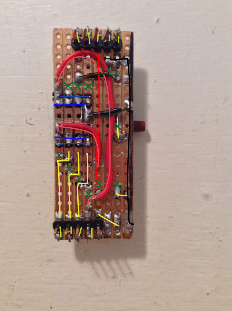
ON MY DIAGRAM
- green X is cut stripboard track
- yellow are data, led/resistor and push button
- blue are headers and socket
- Forgot to indicate capacitor....
- red-vcc
- black-gnd
COMPONENTS
- 10 uf capacitor
- led and 5v correspondent resistor
- momentary push button
- female and male headers
- ic socket
if you want to follow my exact diagram go ahead but i wouldn't recommend it, i have included an overhead view and if you need anything else comment and ill try help as best as i can. I have included a Schematic and will make a fritzing image. Now for the others bits...
Step 3: The 20 MHz Module


This little beauty saved my life, i discovered that i could not bootload my first attinys try as i might, and soon discovered it was a common issue, but then i remembered something...
The factory bootload they came with was 20 MHz external oscillator, but i wanted it to use the internal one and soon found it need the 20 MHz to be re-bootloaded - so i made one! Thank god for the headers!
This module is really designed to be plugged in the headers of the shield but is actually extremely simple.
A crystal runs between pin 2 and 3, the pins 2 and 3 are then connected after each going through a 20pf cap to ground. This can easily be found in the datasheet On page 29
The little board is connected to 2,3 and 4 and the header to pin 1 is simply structural. from the two pictures it should be reasonable self explanatory, feel free to comment if u need help.
Step 4: The ATtiny85 and the Arduino IDE


I give credit to High low tech for most of this page but i have done my best to shorten it
These are the Board files required attinymaster
This can be completed on a breadboard but I made a shield for easy use.
First upload the ARDUINO ISP code to your uno(when running the led on pin 9 fades on and off), the file can be found at the bottom of the page, then place an attiny in the shield if that's what you made, or wire all the connections via a breadboard to the arduino, once the arduino has the isp code loaded the led on pin 9 should fade on and off, now you are ready.
I am not responsible for any damage caused to your arduino or attiny85 in this process, you complete this task at your own risk.
Here we go!
- download the attinymaster file at the top of the page and extract it to your desktop.
- inside should be "attinymaster" and inside that should be "attiny"
- go into your documents, then arduino, it should be full of your sketches
- create a new folder "hardware" with your sketches and copy the "attiny" file inside it, NOT attinymaster
- restart arduino ide,
- You should see ATtiny entries in the Tools > Board menu
- if not comment and i will try help
Now we can set it up
- select you attiny from the boards menu
- select "Arduino as isp" from tools > bootloader
- click "burn bootloader" and cross your fingers!
- if it works continue, if not try again or comment
Now you can upload you programs! i have included the pin diagram for the '85, i recommend opening blink, swapping the pin to 0 and checking and led blinks when you put it on the attiny's pin 5.
most functions are supported but its generally not a good idea to assume- heres a brief list
- pinMode()
- digitalWrite()
- digitalRead()
- analogRead()
- analogWrite()
- shiftOut()
- pulseIn()
- millis()
- micros()
- delay()
- delayMicroseconds()
- SoftwareSerial (has been updated in Arduino 1.0)
Thanks for reading! sorry it might be a little brief but im only 14! please vote for me in the contest if you have enjoyed and feel free to ask questions and make suggestions!
Attachments

Step 5: P.S. - Those Sneaky Headers
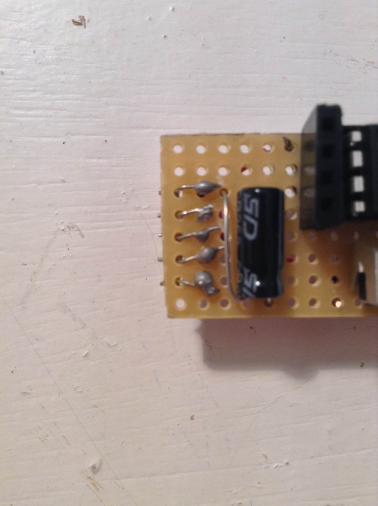
For the shield i needed a way of getting the headers on the wrong side, and after much trial and error i discovered a non-mainstream way, i took some old leads and bent a right angle in the center, and i placed the headers the wrong way up as shown in the pictures with an extra row on their other side.
i put a tiny but of solder on the tips to hold them in the holes, do these first few steps with the headers placed in the arduino for a good alignment. take them out and place the bent leade in one of the extra holes and solder it to its corresponding header, see where im going? Then solder the other end of the lead to the under side and hey presto! an easy solution! feel free to use your own method as this is only a guide and feel free to comment if your confused or have questions.
Again.. Please vote if this helped!

Participated in the
Full Spectrum Laser Contest

Participated in the
Arduino Contest


