

Introduction: Arduino Based Bi-color LED Matrix Tetris Game


One of the electronics DIY kit jolliFactory came up with is the Bi-color LED Matrix Driver Module Kit. This module is designed to be chain-able so that you may daisy-chain the modules together to the number of modules you need to suit your project.
The following are some of the projects built using this Bi-color LED Matrix Driver module:
- Instructable to build a 7 Bi-color LED Matrix Scrolling Text Display
- Instructable to build a Voice Input Arduino Bi-color LED Matrix Scrolling Text Display (Bluetooth + Android)
- Instructable to build a Arduino based Bi-color LED Matrix Audio Spectrum Visualizer
It is amazing to browse through instructables and find projects which may interest and inspire you to embark on the project or ignite new ideas for your project.
Tetris is a tile-matching puzzle video game released in 1984 and it was the hugely successful handheld version for the Game Boy launched in 1989 that established the game as one of the most popular ever.
Just for FUN, we thought we could build a simple Tetris game by daisy-chaining two of the Bi-color LED Matrix Driver modules together driven by an Arduino micro-controller simply by adapting similar projects found at instructables. We searched through the instructables here but did not manage to find any similar Tetris project to work on.
We expand our search to other online sites and managed to find some information which we adapted to build a simple Arduino based Bi-color LED Matrix Tetris game here.
To build this project, basic electronics knowledge with electronics component soldering skill and some knowledge on using the Arduino are required.
You may view the following YouTube video to see what we are building.
Step 1: Building the Bi-color LED Matrix Driver Module

We will be building a two LED Matrix tall Tetris game here driven by an Arduino Nano for this project. We will need two of the Bi-color (Red/Green) LED Matrix Driver Module Kits from jolliFactory. Each of these modules uses two MAX7219 Display Driver ICs to drive a Bi-color LED Matrix. These ICs are excellent because they take a lot of work off the micro-controller and simplify the wiring and logic design.
You can find this Bi-color LED Matrix Driver Module kit from here.
This kit comes with all through-hole components and someone with basic soldering skill should be able to assemble it without much difficulty.
See the following YouTube video on how to assemble the LED Matrix Driver Module Kit:
Step 2: Wiring


After all the LED Matrix Driver Module kits are completed, they are connected together with the Arduino Nano micro-controller as shown in the wiring diagram (LED Matrices not installed for better view).
For the game audio output, we used one 8 ohms 0.5 watt speaker driven directly by one of the Arduino’s digital pins through a 100 ohms resistor. Basic sound tone is used for this project and the low sound volume should be sufficient for a hand-held game with this simple setup.
Four SPST Panel Mount Momentary Push Button Switches are required for the project for navigation and rotation of the Tetris blocks.
Note the use of 10Kohms pull-down resistors on the DATA IN, CLK and LOAD input pins. When power is first applied to the micro-controller or when they are reset, their I/O lines float. The MAX7219 can see this as valid data and display garbage until the micro-controller gains control. The pull-down resistors prevent these problems. To reduce the part count for this project, you may try without the 10Kohms pull-down resistors for the DATA IN and CLK input lines.
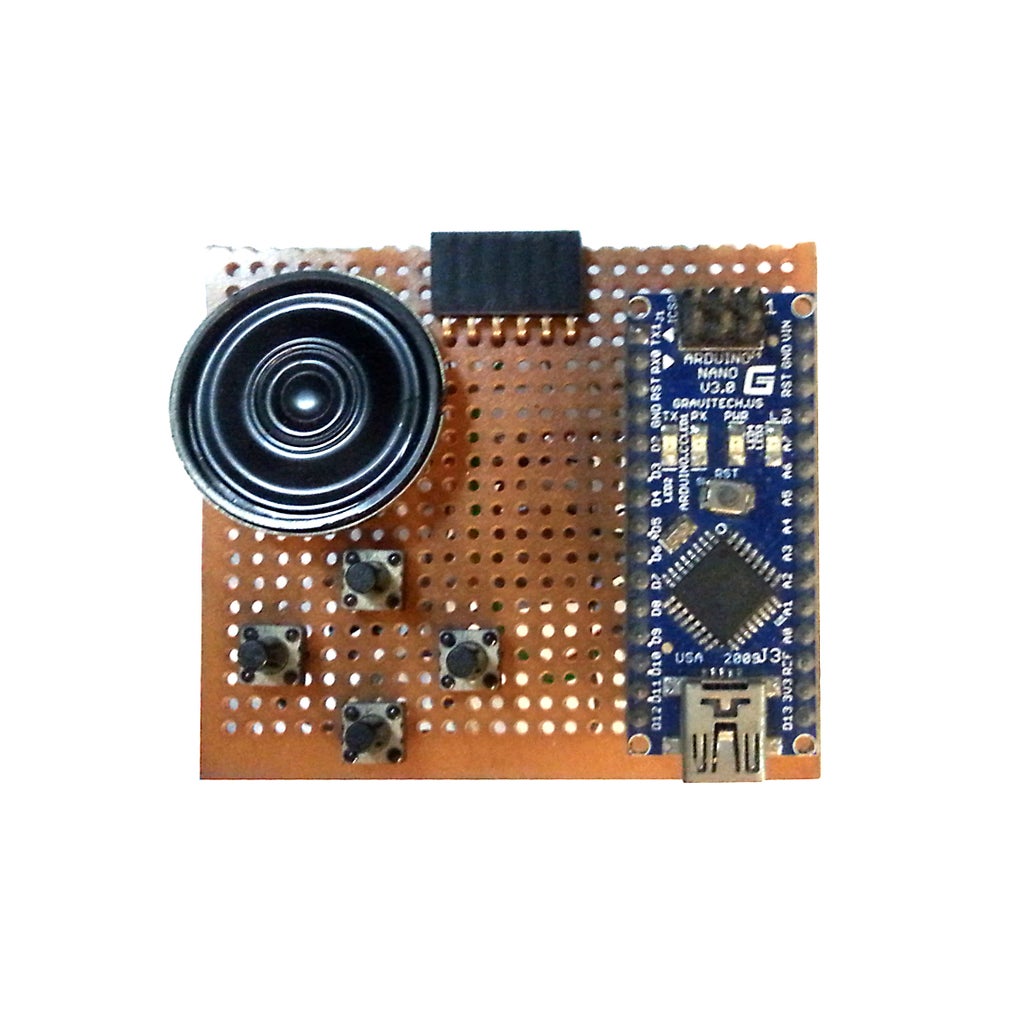
Except for the two Bi-color LED Matrix Driver modules and the four push button switches, we hook up the entire circuit on a small piece of perf-board around 60mm x 60mm in size.
Note that there are four PCB mount push buttons on the perf-board in the photo. We initially used them for the game control but after building a simple enclosure for the game, we decided to use four panel mount push buttons instead for better game control. We parallel wired our panel mount push button with the PCB mount push buttons so game control can now be performed using either the PCB or panel mount push buttons.
Edit:For those who do not want to mess around with too much wiring using perf-board, jolliFactory have designed a bare interface PCB board suitable to build this project. If you are using this interface PCB board, do remember to change the speaker output digital pin from D9 to D8 in the sketch downloaded from this instructable to drive the speaker.
You may find our bare interface PCB board at https://www.tindie.com/products/Nick64/jf-interface-board-1-bare-pcb-board-with-headers/
Step 3: Programming the Arduino Board
The Arduino board needs to be loaded with the Arduino sketch to run the display.
We used Arduino IDE V1.03 for our project. Download the Arduino sketch below for this project.
Download jollifactory_Tetris_V1_1.ino
The Tetris game sketch we have here is very basic without any game levels and scores. You may amend and enhance the sketch.
Note: Having some problems with your Bi-color LED Matrix Display modules? Download the following test program to test each of your modules separately. The display should light up RED, GREEN and ORANGE in sequence row by row to fill up the entire display repeatedly.
Step 4: Enclosure and Assembly


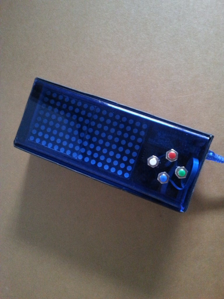

As this project is simply built for the FUN factor with no intention of using it for long, we did not pay too much attention to build a proper enclosure. However, the enclosure built should enable the player to hand-held the gadget to play quite comfortably.
What we have for the enclosure is a cardboard box backing with a blue tinted acrylic protective front with the game control push button switches mounted. We did not even secure the modules to the enclosure as they fit quite snugly in the enclosure.
We will not delve into the detail on how we build our game enclosure here. The pictures show the various stages of assembling the completed sub-modules together.


