

Introduction: Arduino-controlled HDMI Switch


This instructable will show you how to control multiple HDMI feeds to your TV using a microcontroller such as an Arduino to enable and disable transmission with a single control line.
My ultimate goal is to have a robust but flexible means to limit the amount of time that kids can spend in front of the TV, without getting into arguments at turn-off time. Time-limiting applications exist for PCs, but at the time of writing there was virtually nothing out there for TVs in the UK. In the US it's possible to buy things intended for this very job, but as far as I know these only suit US plugs and voltages or they control only composite video etc.
I had it in mind to build an Arduino-based controller with a real-time clock module to provide the timer functionality. The hard bit was how to switch the TV on and off robustly but safely. So I set about considering the options:
1) control the mains power to the TV - very effective but I worry about adversely affecting the TV in the long term and it involves using mains relays etc.
2) control using IR remote protocols - nice idea but power is almost always a toggle I think, and there's no way for a remote device to know the state of the TV, so in practice I don't think this would work.
3) control by switching the HDMI feeds from the various input devices (we don't use direct RF input to the TV anymore) - this could work but HDMI is a fast signal which needs to be routed and switched carefully - you can't just use a few transistors on a protoboard!
I considered options 1 & 2 to be non-starters. Option 3 seemed like the best way to go, except for the problem of how to carry out the switching. Enter the automatic HDMI combiner and switch which can be bought for less than £5 from numerous traders (via Ebay, for example).
I rapidly determined how to modify this very simply so that a 0-5 V TTL signal would control whether it transmitted or blocked HDMI signals. The modification doesn't impair the manual or automatic channel selection within the device.
The modification is very simple provided you are comfortable with Arduino interfacing and basic soldering. It requires the following:
Cheap 3-to-1 automatic HDMI switcher of the type shown above (can easily be obtained via Ebay, for example). It may be possible to use others provided that they function in the same way. UPDATE - see my other instructable for an alternative HDMI switcher which works in the same way and which I found to perform better with some of my AV sources.
Basic electronics tools
Soldering iron
1K resistor
2N2907 PNP transistor
Hot-melt glue gun
Hook-up wire (e.g. 7/0.2)
I will describe only the HDMI switcher modification in the following pages. It's really simple. I have assumed that people undertaking this modification have 'normal skill in the art' and therefore haven't included circuit diagrams or photos of every single stage in the process. The Arduino controller part I leave to the reader for now as it's likely to be tailored to their individual needs. My plan is that the would-be viewers would have RFID passes to let them 'log in' to access their TV minutes, which are shown ticking down on a seven segment display. UPDATE - this work has now been published in another of my Instructables.
Disclaimer: this modification worked for me and didn't seem to harm any of the attached AV hardware, but I can't guarantee its suitability for the application so obviously if you carry it out then it is at your own risk.
Step 1: Remove the Power Supply Diodes From the Switcher PCB
Remove the four screws from the underside of the switcher enclosure.
Pry the two halves of the case apart and remove the circuit board.
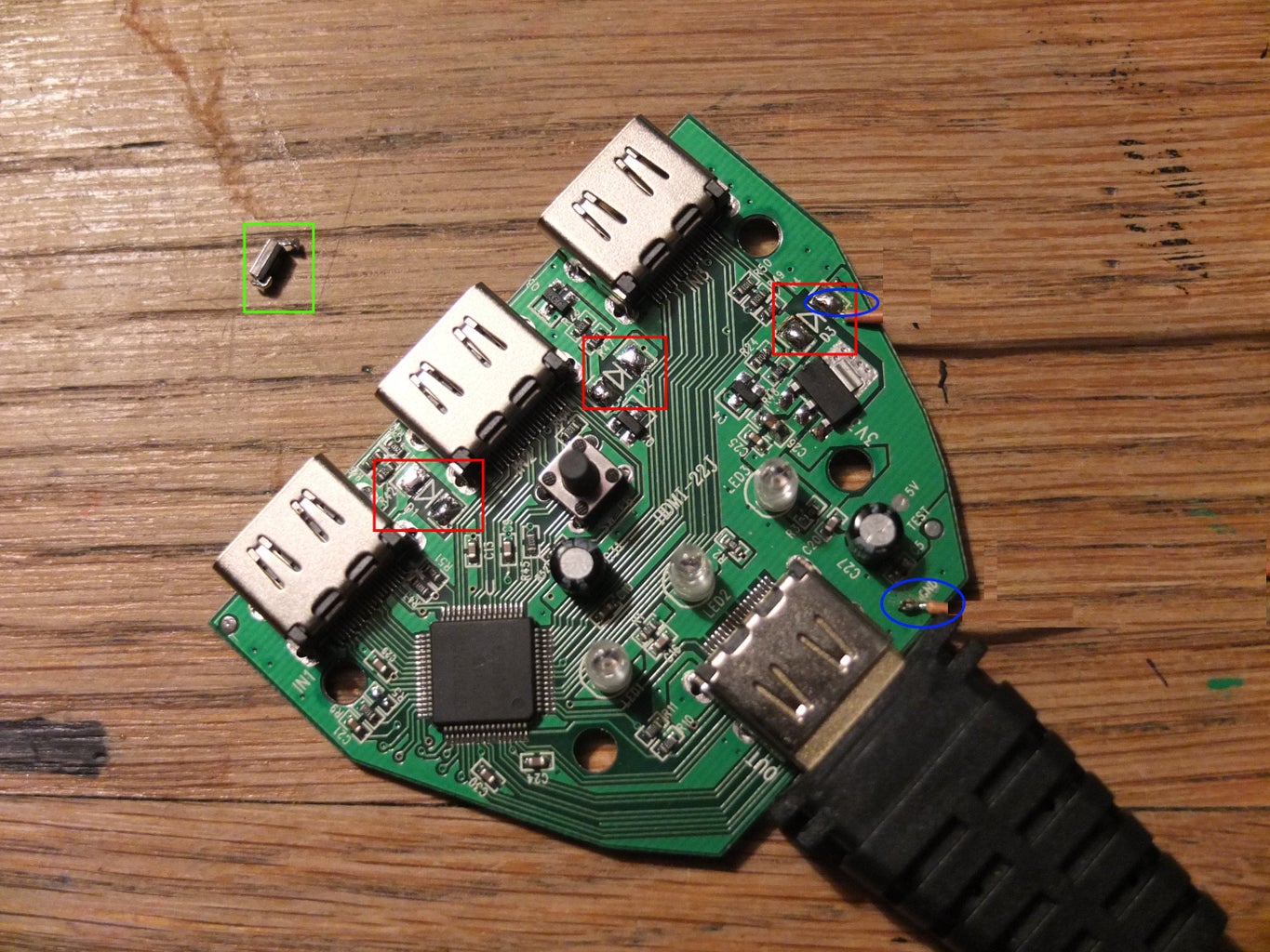
Identify the three surface mount diodes D1 to D3, whose locations are marked in red on the figure. These diodes route a +5 VDC supply from incoming HDMI leads onto the board power supply section; the board derives its power from these leads.
Remove the diodes (one is shown marked in green) using a soldering iron to pry them from the board. This effectively disables the board as the switcher IC can't obtain external power. Note that the photo for this step was taken AFTER the diodes had been removed.
The modified circuit board can now be enabled externally by providing an external +5 VDC supply to the power supply section on the board. The +5 VDC should go to the cathode pad of D3 and the supply ground should go to the ground pad near the output HDMI lead (marked GND on the board if you look hard enough). These are marked in blue on the figure.
This is the essence of this hack - control the power to the board and you control whether HDMI is transmitted or not. The manual / automatic switching of individual inputs is retained following this modification.
Step 2: Install a Transistor Switch on the Switcher PCB

The Arduino can't source enough current from a single pin to drive the HDMI switcher board. Its 5 VDC supply rail can source approximately 400 mA however. So the next step is to install a high-side PNP transistor switch to allow the Arduino to control the board from its own power supply via a digital output.
I used a 2N2907 PNP transistor. This was mounted dead-bug style on the switcher circuit board using hot-melt glue. In the figure the rounded side of the transistor faces the outer edge of the board. It's important to keep all the additional components / wires low down on the board so that the enclosure cover will fit back on afterwards.
A black lead was used to connect the Arduino ground to the ground pad on the switcher board.
A red lead was used to connect the PNP's emitter to the Arduino's 5 VDC pin.
An orange lead was used to connect a digital output on the Arduino to the base of the PNP, via a 1 kOhm resistor. I used pin 13 as it's connected to the LED and blink makes a good test sketch. This orange lead is the control line for the high-side switch.
The PNP's collector was connected to the D3 cathode pad on the switcher board.
Hot-melt glue was used liberally to ensure that all the leads and components were secure and that no shorts could occur between the resistor, transistor and the switcher board.
I filed some small grooves in the side of the enclosure to allow the wires to pass through. Provided that the dead-bug installation has been done carefully, the enclosure cover should fit back on without any problems.
Step 3: Conclusion
Okay - that's pretty much it. As it's a PNP high-side switch, HDMI transmission is asserted by setting the control line LOW (0 V). Setting the control line HIGH (+5 V) disables the switcher and thus prevents display of any HDMI signals. Don't worry though - if your resourceful urchins unplug the power supply to the Arduino, they'll lose the all-important 400 mA 5 V rail which will completely inhibit HDMI transmission.
Obviously to use this switcher as a means to control access to a TV, you need to enclose it in a hard-to-open box which encloses the controller, switcher and the plugs of all the HDMI input leads, with holes for the input leads small enough to prevent them from being pulled out and plugged directly into the TV. I intend to mount everything (switcher, controller, display etc.) into a single attractive enclosure that can go next to the TV.
It goes without saying that this will be effective only if your TV is being used as an HDMI monitor. If you leave an RF lead plugged into the TV then that will still be available. In the UK it seems to be increasingly common to use a PVR to take the RF input and provide the TV signal over HDMI, so all you need to do is remove the RF input cable from the TV and hide it or alternatively remove all the channel tuning, to prevent your kids bypassing your controls.
I hope someone finds this information useful. Good luck with building the controller - when I've finished mine I shall update this post.


