

Introduction: Arduino-controlled UV LED PCB Exposure Box


Why make an exposure box?
Like many Arduino lovers, once I began creating larger projects I obviously did not want to keep them on a fragile breadboard. As many people do, I started to assemble my projects on cheap prototype boards. While these boards were fairly rugged, their layouts were confusing to say the least and were basically organized chaos! So I learned how to etch my own circuit boards. While there are several ways to go about making your own boards, with the two most popular being toner transfer method or the photo-resist method .. I chose to go with photo-resist using pre-sensitized boards. This involves designing your board in software such as Eagle CAD, printing your circuit out on transparency film with a laser printer, exposing and developing the board with a light source, and finally etching the board with ferric chloride solution. My very first board came out perfect to my surprise but it was pure luck. As I made more boards I quickly found out that I never achieved the same results twice. What I found out is that the exposure time and the distance between the board and the light source must be EXACT every time. I was over or under exposing my boards most of the time. I wanted to make my own fool-proof exposure box that #1 would expose each and every board in the exact same way with evenly-distributed light and #2 precisely time the exposure of every board down to the second. I also knew that using UV light would greatly reduce the required exposure time.
It was well worth the effort! I found that the perfect exposure time for any board was only 2 minutes – 15 seconds for a 4x3 PCB, which is generally the maximum size of nearly all of my projects. This exposure box is specifically made for 4x3 inch boards, but can be scaled up if your projects demand larger boards.
So in the end I simply print and cut out the 4x3 transparency film, lay the film glossy side down in the exposure window, peel and place my blank PCB into the window (which fits like a glove), enter my exposure time, press START and walk away!
And again keep in mind that I designed this box especially for 4 x 3 inch boards. You can easily scale the project up or down by simply adjusting the window size AND the number of UV LED's used. I would estimate 9 LED's for every square inch of copper.
Step 1: Next: Gathering Your Parts, Tools, and Software...
Here are some links to have on hand that you will need later
Eagle CAD Free Edition
http://www.cadsoftusa.com/download-eagle/freeware/
The Arduino IDK
http://arduino.cc/en/Main/Software
The project files and code will be supplied as a .zip file in the last step!
Step 2: Required Parts and Tools
You can make this project as elaborate as you wish. I'll dedicate this step to listing all of the parts and tools that I used in my design.
Exposure box parts list:
Tools:
Drill and small drill bit set
Dremel tool with cutting disc
Razor blade or Exacto knife
Needle-nose plyers
Phillips screwdriver
Breadboard (optional)
Hot glue gun
Soldering iron
PCB etching materials
Timer Board:
Jumper wires
Arduino Nano
Female and Male Pin Headers
DC Power Jack 2.5mm
Power switch SPST On/Off
16x2 LCD module
4 x Momentary Push Buttons, N.O.
2 x LED
4 x 1k ohm 1/4 W Resistors
2 x 680 ohm 1/4 W Resistors
Buzzer / speaker
1 x 1k ohm Potentiometer
1 x Reed Relay
1 x 2N4704 General Purpose NPN Transistor
1 x 220 ohm Resistor
14 - 20 VDC Wall Power Supply
1 x 7805 5V Fixed Voltage Regulator
1 x 7812 12V Fixed Voltage Regulator
2 x Regulator Heatsinks
2 x 0.1uF Ceramic Non-polarized capacitors
2 x 1uF Electrolytic Polarized capacitors
Proto OR Strip Board may be desired for push button panel
1 x Presensitized PCB 4" x 3" and developing/etching solutions
Enclosure:
Approx 6" x 8" x 5" deep Plastic Project Box
Approx 5" x 4" Plexiglass 1/8" Thick
Scrap piece of plastic approx 5" x 4" flat - 1/4" thick for light board mounting
UV LED Light Board:
1 x Wire Screw Terminal
21 x 100 ohm 1/4W Resistor
63 x 5mm UV LEDs
1 x Presensitized PCB 4" x 3" and developing/etching solutions
Software:
Arduino IDK (http://arduino.cc)
Eagle CAD (free version)
Step 3: Schematics and Features


The control board's power supply takes a DC wall adapter voltage of at least 14 volt DC and creates two voltage rails using the 7812 / 7805. 12 volt supply drives the 63-LED board while 5 volt supply is for the Arduino and logic. The 5 volt regulator is supplied by the already regulated and filtered 12 volt rail. A RTC (Real Time Clock) chip was not really required for this project as using delay(); was suitable for a simple timer. The button panel consists of a start button, minute select, seconds select, and clear button. Power and status LED's and the 16x2 LCD module for displaying timer and messages are located on the top of the box, below the UV light window.
Light Board Schematic:
The UV light board has 7 Rows / 3 Columns of UV LED's with 3 within each 'cell'. It is build on a 4 x 3 inch PCB. Forward voltage to each LED is about 3.5 volts with each cell having a 100 ohm current limiting resistor. The series/parallel circuit is driven off the 12 volt supply via a reed switch. I used a reed switch instead of a switching transistor to avoid ANY voltage drop therefore acheiving the full brightness of the LED's. With a potentiometer, you could add a brightness adjustment if you wanted to.
Assembling the light board...
Above are the schematic, PCB design, and an assembly video for the light board. Eagle files and code will be provided in the final step. The next steps go into the timer/control circuit board.
Step 4: Timer/Control Board Operation, Schematic, PCB


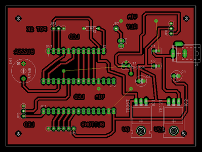
Actually the timer/control PCB was my first test subject using the UV LED window. I simply powered up the light board for 2 minutes, 15 seconds with a 12 volt bench supply to expose the box's own control board. The results were much better than I ever expected.!
Buttons Board Schematic
Design this any way you see fit. I opted for a simple prototype strip board with the push buttons, resistors, and pin headers. Drilled some holes and mounted it to the front of the project box.
Step 5: Choosing and Preparing the Enclosure

Preparing the Enclosure
The project layout is optional, but I decided to cut holes in the enclosure for the exposure window, the LCD display, and status LED's on the top as seen in the images. The DC power and ON/OFF rocker switch holes were cut out on the side and setup button holes drilled on the front. Use an exacto or razor blade to trace the outline of a 4 x 3 PCB on the top of the box. Carefully cut this out with a dremel tool, and smooth the edges with swipes of a razor blade. Cut another hole for the LCD below the exposure window for a secure and tight fit of the LCD module. On the inside of the project box, apply some super glue around the edges of the exposure window cutout. Carefully position the piece of plexiglass over the window cutout, making sure to leave some overlapping plexiglass on each side, and let dry. Use a gluegun along the plexiglass edges for more stability. Insert the LCD module into it's cutout window with it's ribbon cable/wires attached. You can use hot glue, screws, or both to secure the LCD. Using hot glue alone worked great for me as the LCD fit nice and tight into it's cutout. As needed, drill / cut holes for your DC input jack, switch, status LED's, and push buttons. I used a blue LED for a power indicator and a red LED for when a board is being exposed. Choosing the right drill bit made a snug fit, with just a small amount of hot glue to secure the LED's from behind.
Now a 4x3 photo-sensitive PCB will fit like a glove in the window that you made. The light board will later be secured inside the box aligned with the exposure window.
Step 6: Eagle CAD and Arduino Resources

Below are the Eagle CAD files and Arduino code used on my exposure box. I've attached some build progress and demo videos as well.
Why you should vote for this project in the Arduino contest!
While I find each and every Arduino project super cool no matter how complicated it is, many times the final product will be transferred from the breadboard to some sort of DIY circuit board. We can all agree that proto/vero boards are fairly rugged but cumbersome. Having a custom PCB exposure box in your arsenal guarantees that with a little patience you CAN get very rewarding results making high quality circuit boards, and cost a fraction of what a board house is going to charge you.
Final demo video and other's I made along the way...
Another demo video...
Making the UV LED light board...
Project CAD and Arduino Files:
Feel free to contact me if any assistance is needed as I am happy to help!
Attachments


Participated in the
Arduino Contest


