

Introduction: Arduino Controlled Automated Blinds With Web UI

This instructable is a detailed guide on how to build an automated controller to run a motor that can operate the opening and closing of blinds. The controller enables the blinds to open and close based on a schedule, room temperature and out door luminosity. The controller settings can be set up via a web UI which enables a user to open or close the blinds manually or place them on a schedule with certain parameters.
This project will guide you through creating simple circuits for the sensors, hacking the motor shield so it can be stacked with the arduino and ethernet shield and implementation of the code (note all code is provided and is fully commented). The project is laid out in the following manner. First the controller and system will be constructed. Then the logic behind the code will be explained. The last page will contain the code and link to download so it can be installed on the arduino.
So I hope you enjoy this instructable, gain from it and most importantly have fun.
Table of contents:
1.Requirements and parts
2.Wiring the sensors.
3.Wiring the arduino and shields.
4.Hacking the motor shield.
5.Code logic.
Step 1: Requirements and Parts
This project is fairly simple to create and set up since the most difficult part, the code, is fully provided. The setting up the arduino and shields is fairly straight forward. Below is a list of parts you will need for this project. I have also listed the prices for these parts if you need do not have them. Most of these can be ordered from Adafruit, Sparkfun or the robotshop.
1. Arduino ($30)
2. Ethernet shield ($50)
3. Motor Shield ($20)
4. Analog temperature (TMP36) sensor ($2)
5. Photocell ($1)
6. 20 pin 0.1" Female Headers ($3)
7. Breadboarding Wire Bundle (6)
8. Breadboard friendly 2.1mm DC Jack ($1)
9. 12 V Stepper Motor (14)
10. 100 ohm resistor
11. MicroSD card (1gb card is good and can be found for as little as $2).
12. 2 Full breadboards ($14)
13. 12V AC adapter. (powers the motor only)
14. battery pack for the arduino
Remember, all these parts can be used for other projects, so don't worry too much about the cost because you'll be able to use them in many more projects, unless of course you are gonna use this as a permanent installment.
Equipment needed
1.Soldering iron
2.Soldering Fan
3. Small screwdriver.
Step 2: Wiring the Sensors
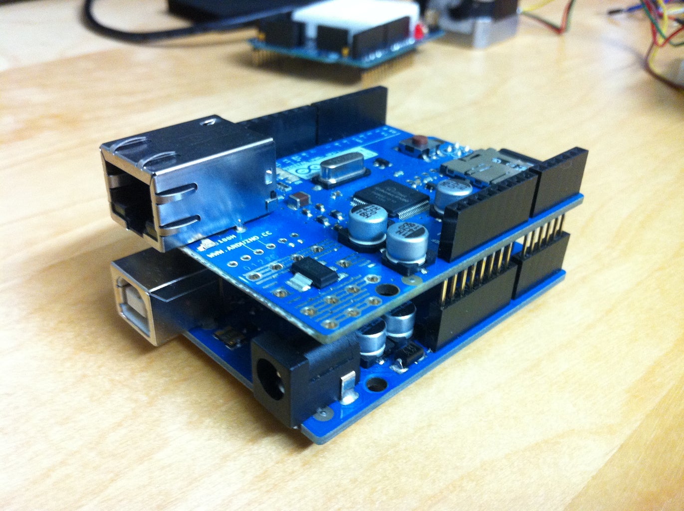
Step 1: .
Combine the aruino with the ethernet shield.
Step 3: Stepper Motor and Motor Shield
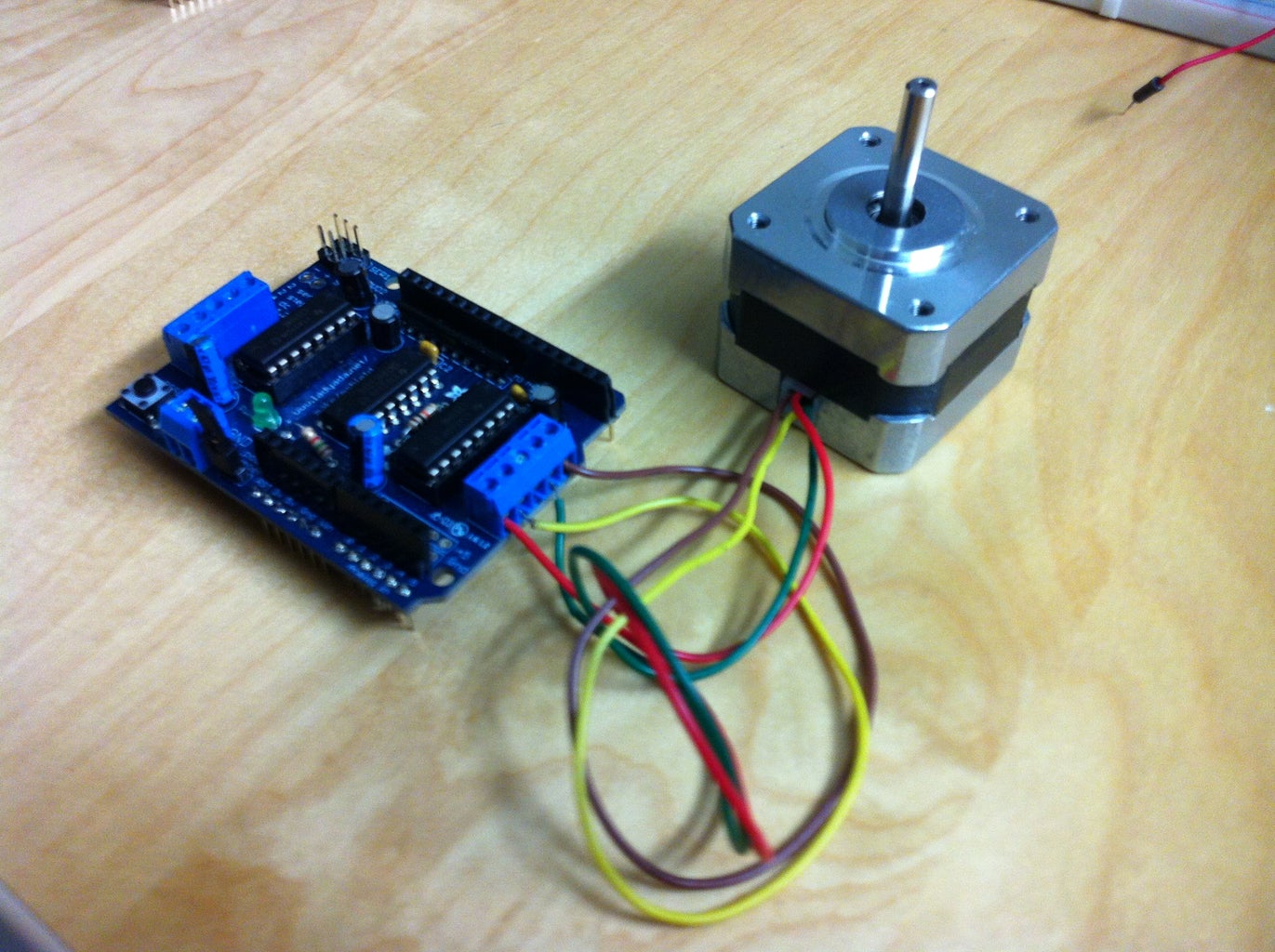
Connect the 12 V Stepper motor to the motor shield in the M3 and M4 slots. Instructions on how to solder the motor shield can be found here: http://www.ladyada.net/make/mshield/make.html
Step 4: DC Jack
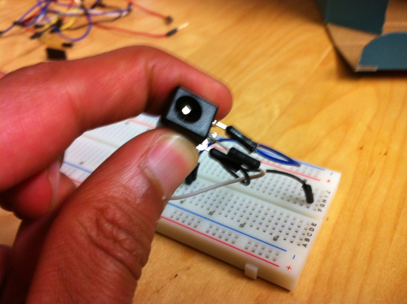
If you have the breadboard friendly 2.1mm DC jack, plug it into the breadboard. Place it near the edge of the board., Later all of the ground ports will be placed in series with the ones from the DC Jack. In the image above, three wires were soldered to the DC jack to extend it length.
Step 5: Temperature Sensor
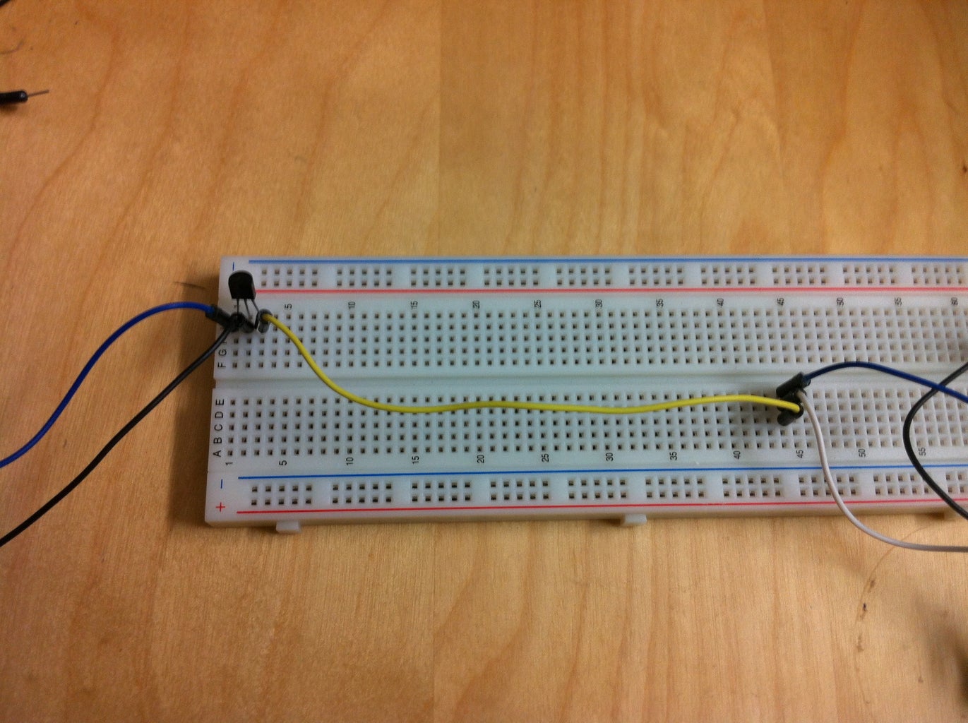
Place the analog temperature sensor in the breadboard as shown above. The first pin is power, the second is output and the third is ground. Wire the ground to the in series with the ground pins for the DC jack.
Step 6: Photocell

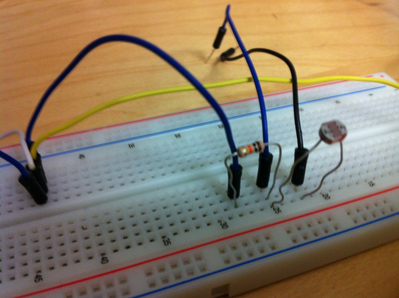
Place the photocell on the breadboard and connect a resistor to it as shown above. The pins are in the same order as on the temperature sensor. Again connect the ground to the ports we are using for all the ground connections.
Step 7: Hack
Now place the motor shield in the second breadboard with the motor facing away from the arduino (as in the image above; notice that the motor is not in the picture).
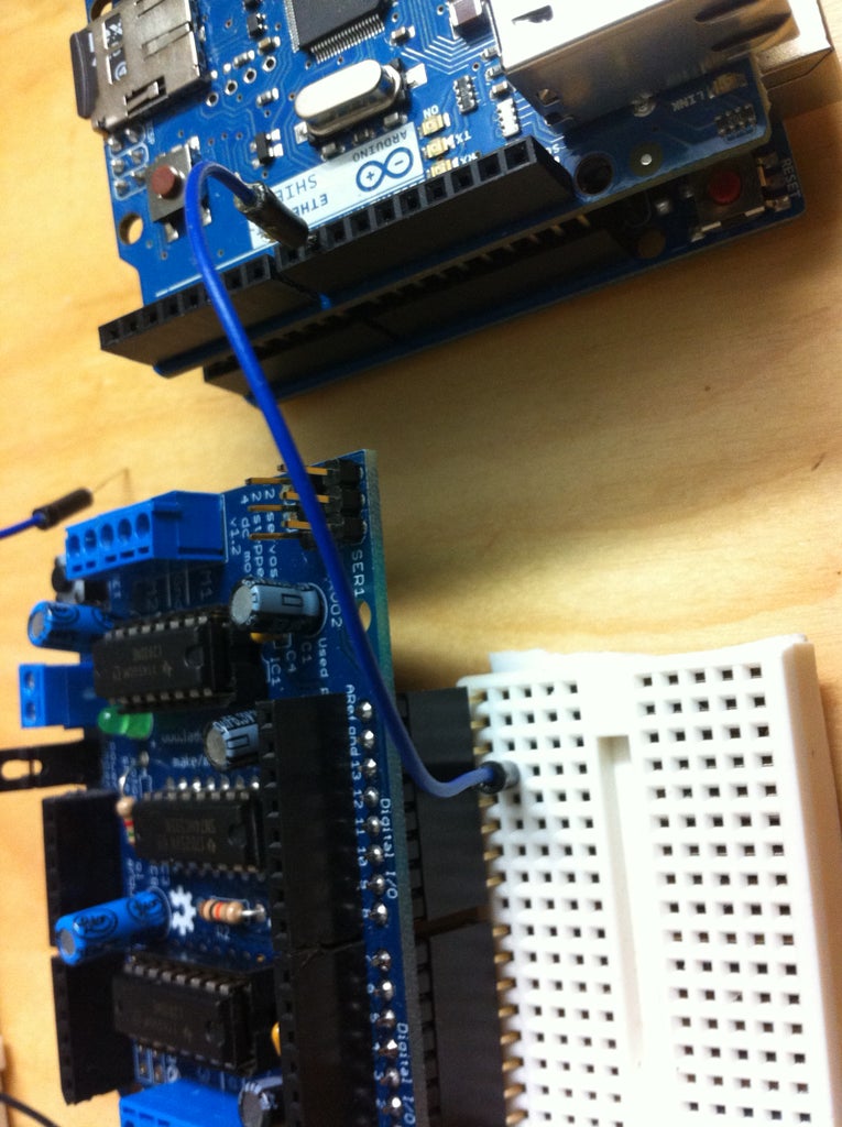
Now for a hardware hack. The arduino communicates to the ethernet shield and motor shield on several different pins but pin 12 is common to both and this causes conflict. To fix this, we are gonna do a software hack so that data the arduino usually sends through pin 12 goes through pin 9 instead. First wire output pin 9 on the ethernet shield to the input slot that matches with 12 on the motorshield.
Now go find motors.h on your computer (usually in the arduino file under mydocuments/arduino/libraries) and open it up. Find the line #define MOTORLATCH 12 and change that to a 9. Save this file.
And there we go.
Step 8: Wiring Outputs to Inputs

Now finish wiring the rest of the output pins on the ethernet shield to there corresponding pin on the motor shield (except for pin 9 and 12).
Step 9: Second Breadboard

Connect the motor shield to the breadboard as shown in the image.
Step 10: More Wiring
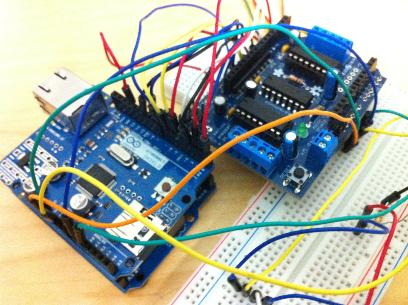
Connect the out put pins for 3V, 5V Gnd, 0 and 1 in series to thier corresponding ports on the breadboard for pins on the motor shield. For example, in the image above, the orange wire goes from 3 V on the enternet shield to 3 V on the motor shield.
Step 11: Giving the Motor Shield Power

Connect a wire (teal in the image above) in series with the power output from the DC jack and wire this to the port on the breadboard that is in series with the VIN port on the motor shield.
Step 12: Grounding
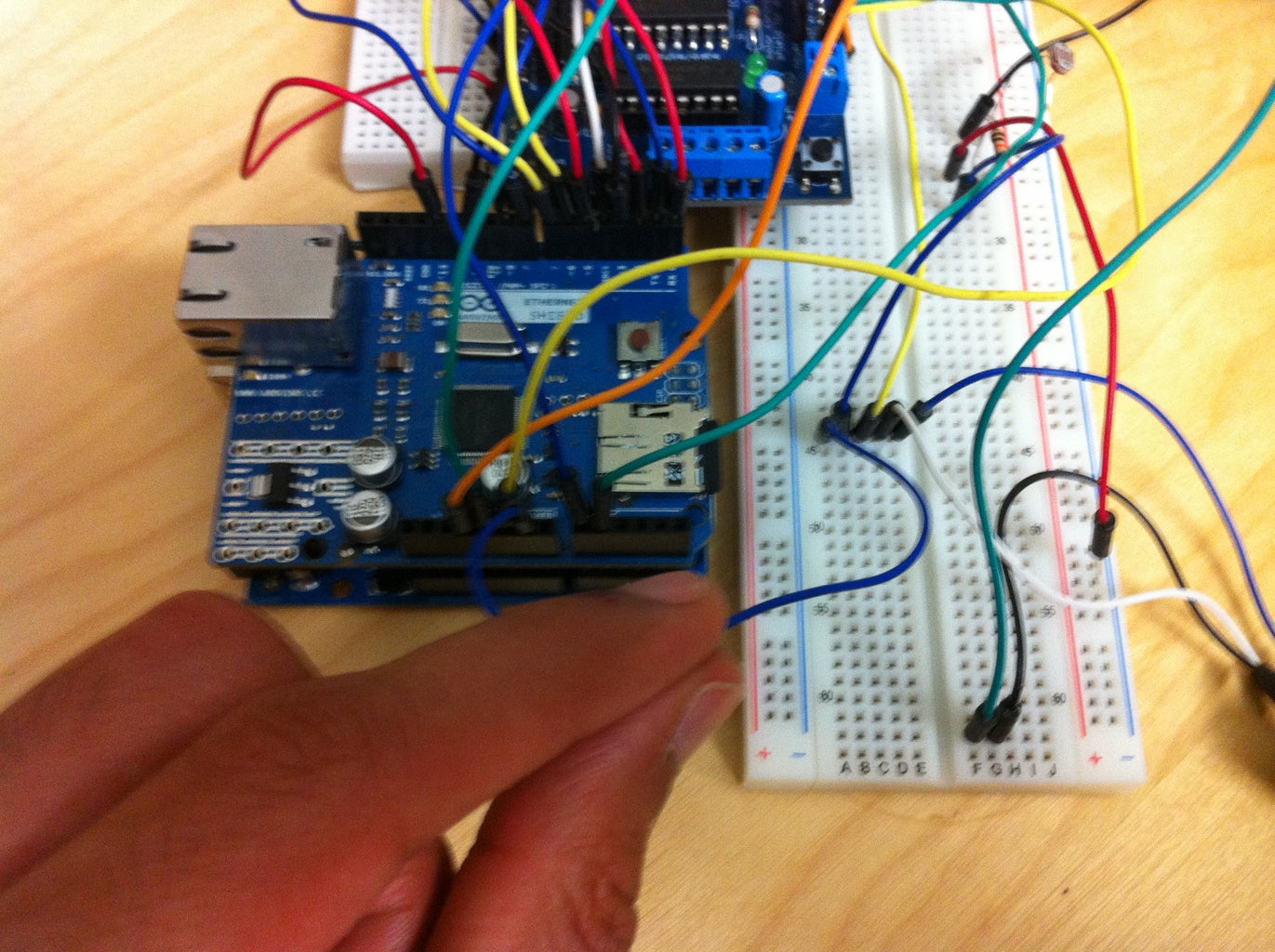
Now connect all the ground wires that are in series to the ground port on the ethernet shield. Observe the held blue wire in the image. Just as a mention, don't forget to place a micro SD card in your ethernet shield.
Step 13: All Done

No finish by taking the power wire for the temperature sensor and connecting it to 3 V on the motor shield. Do the same for the photocell but connect to 5 V (remember that first wire is power). The second wire goes to the input on the motor shield. Place the temp sensor on 0 and photcell on 1.
AND YOU ARE DONE CONSTRUCTING THE DEVICE.
Step 14: The Code
A detailed explanation for the code will be coming soon. For now you can download the code below and run it. I have commented throughout to make modification easy.
Important:
1. you will need to manually enter the IP address of your device and its MAC address into the code before running. You can get the IP address after connecting the ethernet shield to a router and loading the DHCPaddress program found under exmaples in the arduino sketch program.
Go through the code and enter your IP address anywhere it says or you notice an IP. There is only 3.
DOWNLOAD HERE: http://www.2shared.com/file/guPvu-HK/WindowBlindsSever1_4.html
Step 15: Final Output


Once the sketch is loaded, you will be able to access the web UI via the IP address. It should appear as the images above.
The program works the following way:
-Via the web UI you can maunually open and close the blinds.
-You can also set a automatic timer that will open and close the blinds based on the following conditions.
If temperature exceeds the temp entered by user, the blinds close, else open.
If brightness is below luminosity entered by user, blinds close, else open.
else it will open and close at the times specified.
Step 16: Running Your Blinds
The motor shaft can be connected in various ways to blinds to operate them. Easiest way to implement this is to use IKEA rollar blinds and attack the motor to the main shaft of the blinds. The design I have shown you here is just to give an idea of the set up of how such a system would work. Modifications are needed on your part to make it fit into the set up you have.


