

Introduction: Arduino Decision Box. (Attiny85)


So I was a bit bored this weekend (actually I wrote this some months ago) and since I had ordered a bunch of Attiny85 chips the week after I decided to make a quite random project with them.
This is a decision box, it takes decisions for you by showing a green or a red light (it can also show orange if we programmed it to combine both colors). It's made from wood and it has an aluminum plate to cover it all, I painted black because small wood objects tend to get quite dirty.
If you want to build one you'll need the following materials:
- Wood (my final box is (3x3x3) cm)
- Red/green led with common cathode (negative leg at the middle)
- A pushbutton (you might want to get one long enough)
- Aluminum plate. (3x3x~0.1) cm
- 4x small wood screws.
- Thermofusible glue
- Attiny85
- 3V button cell.
- 100, 500 and 10000Ω resistors.
- 8pin chip socket (if you plan to reuse the attiny)
- Tilt switch (optional but highly recommended)
- Thin wires (preferably non solid core)
These tools are also recommended:
- Dremel (performs better in this kind of tasks than a simple drill)
- A saw (jewelers saw) is needed if you plan to cut the wood cube and aluminum lid by yourself.
- Sandpaper (when it comes to making a perfect square there's nothing like sandpaper)
Step 1: Making the Body
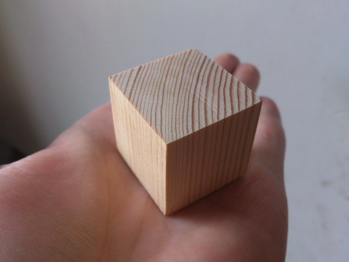
Cut the wood cube, you can also use pre cut slats, this can save you a lot of time.
As always make the marks with the ruler and start to cut, unless you have very precise saws like a bandsaw or a circular wood saw the chances are you make the cube a bit irregular, this is were the painful method of measuring and sanding comes to play, mark the places you want to sand with a pencil and sand them placing the sandpaper over a flat surface.
If all goes well it should look like the picture.
Step 2: Hollowing It
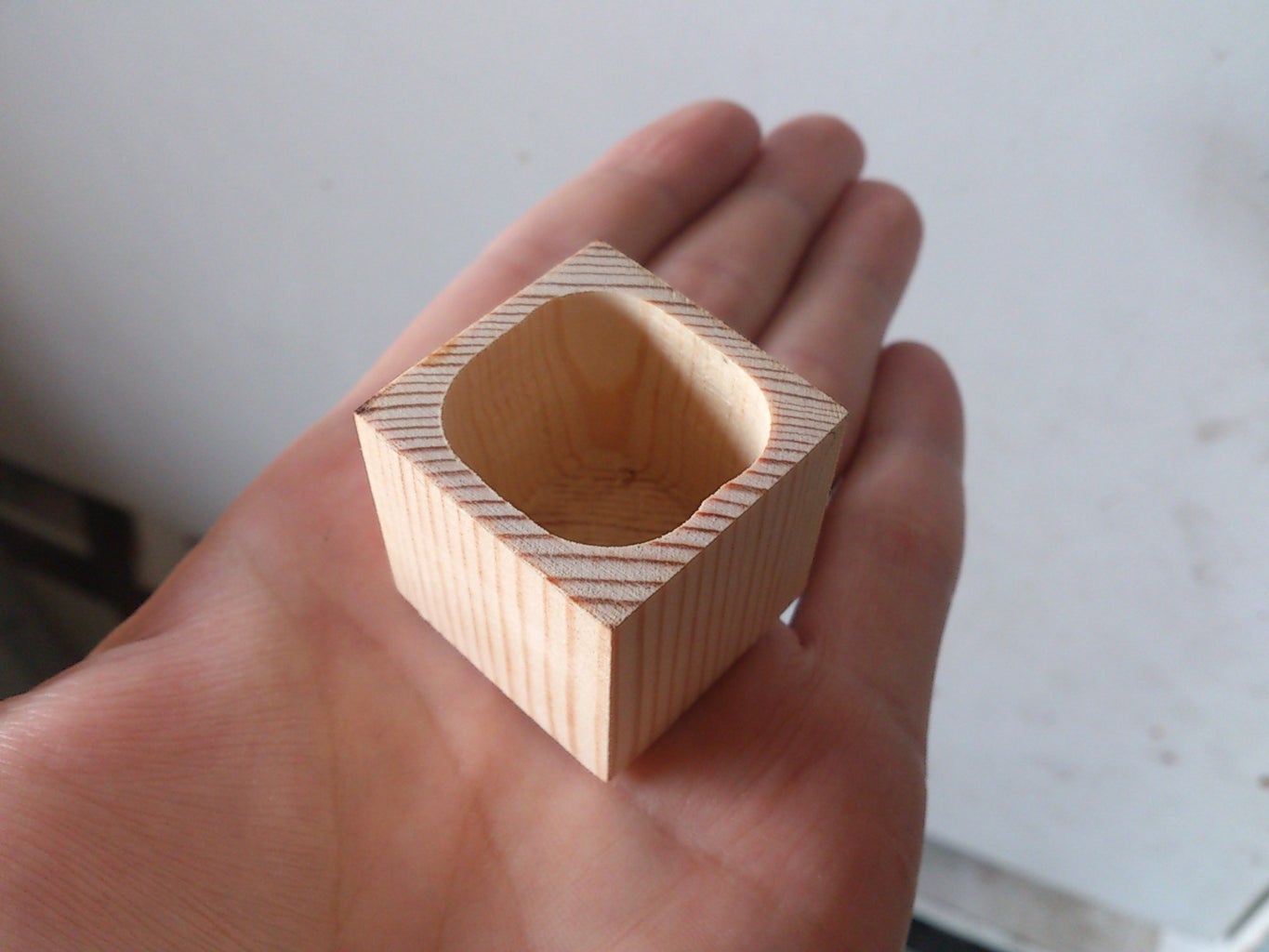
Now you have make an empty space inside it, this operation is quite delicate and should be made with care.
What I did was to place the cube at my table clamp using a rag, so it doesn't leaves marks on it, then with the Dremel I used a normal drill bit to make the initial holes, it's very useful to put a bit of tape on the bit to avoid drilling through all the piece.
Once I have a bunch of small holes, I used the carving bit of the Dremel to carve a nice hole, finally with the sandpaper bit I smoothed the walls.
A 0,4 - 0,3 mm wall thickness is recommended.
IMPORTANT: leave more space on the corners where the screws will be placed, this grants you a bigger margin of error.
Step 3: Accomodate the Components
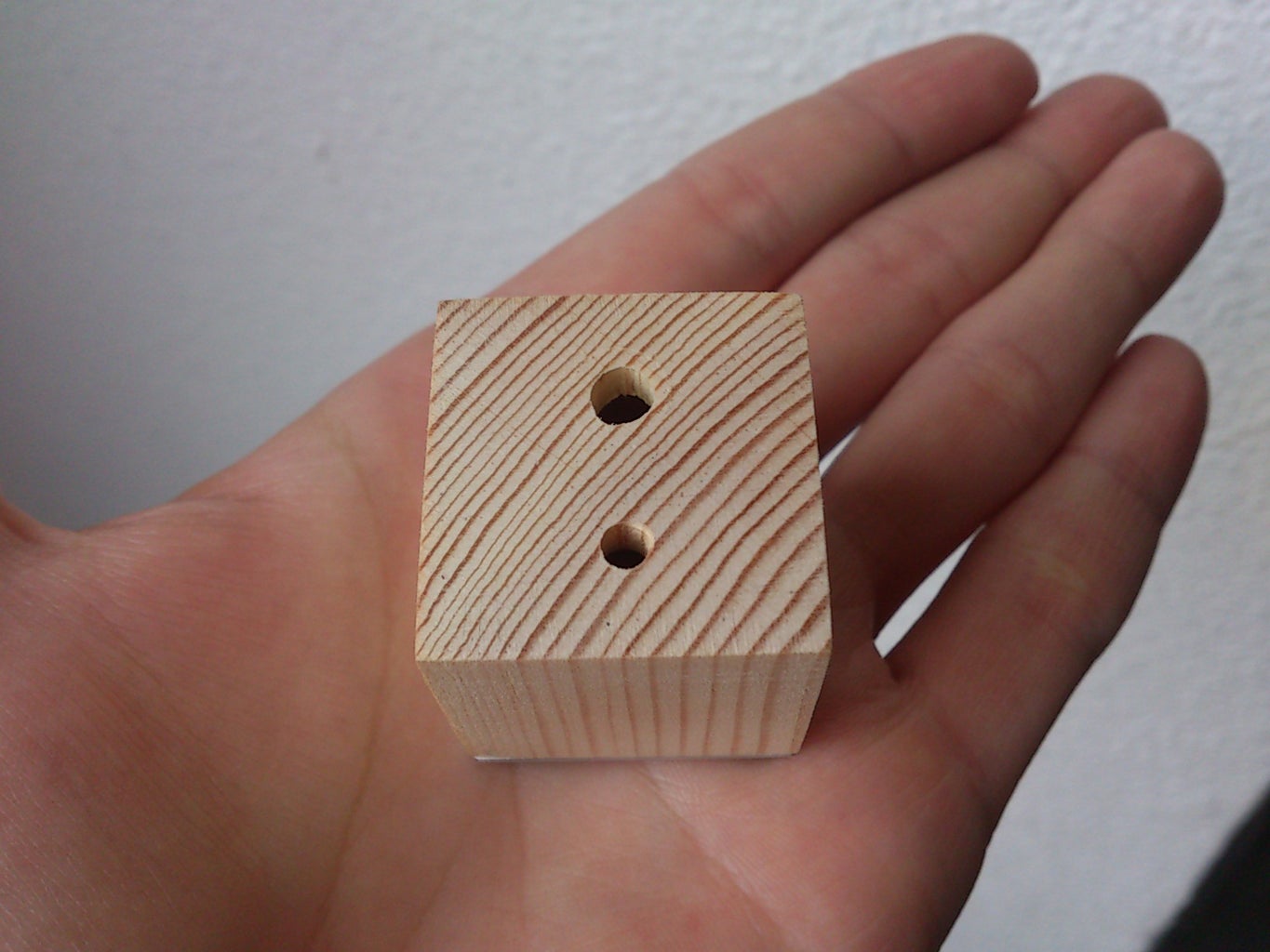
Once you have a nice empty space where you can allocate your components you can make the holes for the push button and the LED , at this point you have two main options:
a) Drill the holes in the wood.
b) Drill the holes in the aluminum plate.
If I had the chance do this again I might make the holes at the aluminum plate because the pushbutton becomes easier to install since the thickness of the wood makes you have to use a long button, also when you unscrew it the whole thing comes out, if you do it the other way the components have to be stick to the wood and this might be quite annoying. The problem of attaching the components to the aluminum plate is the thermofusible glue doesn't sticks to metals too well and it could end flimsy.
As always mark the right spot and have a firm hand.
Step 4: The Lid


The aluminum plate is easy to cut off, just grab the box and with a pencil mark the outlines of the bottom of it, then with care, cut it out with a jeweler's saw, you can later sand the corners and edges so they end smoother.
TIP: because the bottom of the box is probably going to be a bit irregular is useful to make a mark at the same corners of the box and plate so you can later align them correctly.
To make the holes get an appropriate bit and mark the points where you have to drill by making lines 3mm away from the sides of the plate.
TIP: to make sure the bit doesn't moves and scrapes the metal you can punch a little hole with a pointy screw and a hammer, that will keep the bit in place, also clamp the plate tightly with a rag to prevent scratches, don't drill it holding the plate with your hands, you could cut yourself if it get's stuck, believe me, that happened to me once.
Step 5: Placing the Lid
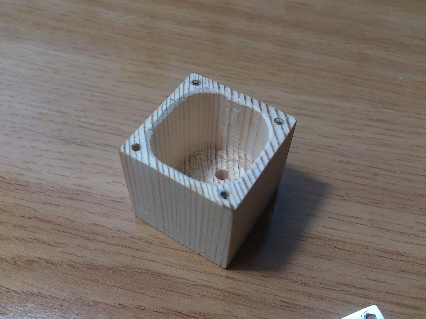
Once you have the holes in the plate you can drill the holes at the bottom of the box using it as a guide, now is when the markings you made to keep the pieces aligned are useful.
Use a Dremel or drill bit slightly thinner than the diameter of the screw.
You can sand the aluminum lid later as if you just wanted to sand one side, just make sure it's tightly screwed and that you go to the direction where the wood part points and that you don't pass over the same spot twice. Aluminum powder is very dirty and easily stains the wood.
Step 6: Making the Circuit


Now comes the electronic part, all the information you need is at the picture shown above, make sure you have tested it properly before making the definitive circuit.
The 10k resistor is to eliminate noises (debounce the button), the 500 resistor is used to consume less energy when the button is pressed, but the Attiny still detects it as high
The tilt switch is quite useful because with a closed box you don't want to be opening and closing it all the time, if you want to turn it off, just flip the box and let it there, the tilt switch will deactivate the Attiny85 so no energy is consumed.
The tilt switch I built gives some problems, I would rather buy a mercury or a more stable one.
I managed to fit it all inside of it without too much trouble, I glued the switch and the LED first with thermofusible glue.
The battery is attached with electrical tape, I couldn't find a simpler and thinner way to do so.
Step 7: Uploading the Code
The code this project needs is really simple, it just has a random() function seeded by a micros() function and then some more functions to turn on and off the LED's depending on the random output.
As always remember that to upload the code to your Attiny85 you must go to >Tools>Programmer>Arduino as ISP and Tools>Boards>Attiny85 1MHz clock.
You can download the code here.
Step 8: Some Final Comprobations.
To check if the random function works properly I've taken note of 80 results, ending with 44 red and 36 green, I find it fair enough, it doesn't seems to show any pattern (thing that would be very strange if it's seeded by micros()).
As you have seen I've painted the box black, this is because such a small object tends to get dirty very quickly and the black color also highlights the grain of the wood. The black color comes from a thick permanent marker, it just does the job.
Step 9: The End

Now you have a random decision box, use it with caution, even the slightest decision can have more power than what you can imagine.


