

Introduction: Arduino Gms Controller for Webasto


This is a simple project where you can change the relay state by sending a text message to the GPRS shield connected to arduino. This can easily be modified to control alot of different projects.
I have seen alot of people building these with arduino and bluetooth and GPRS and people asking how it is build but none of them has been very helpful and only promised to sell kits to do this. I decided to support the open source community and write a instructable of my own project.
There are few "extra" features here, battery voltage measurement so that the webasto won't be turned on if the charge in the battery is low. Power down feature for the shield when the charge goes under a set limit it also sends a text message to the cars owner warning him that the batterys charge level is low. The measurement is not super accurate but gives you an idea what of the batterys charge. More on the subject of voltage and state of charge in the battery can be found here.
http://www.energymatters.com.au/components/battery...
All of those voltage value can be changed in the software by changing value of one variable.
If you try to recreate this instructable, you do so at your own risk.
English is not my first language so there propably are some spelling mistakes in here and I took the photos with my phone so they are not really good quality.
I haven't tested this on the square clock model of webasto or Eberspächer or any other types of car/boat heaters but if it has a pushbutton start this should also work as a remote for that too, you might need to adjust the relay ON time a bit.
Step 1: Parts
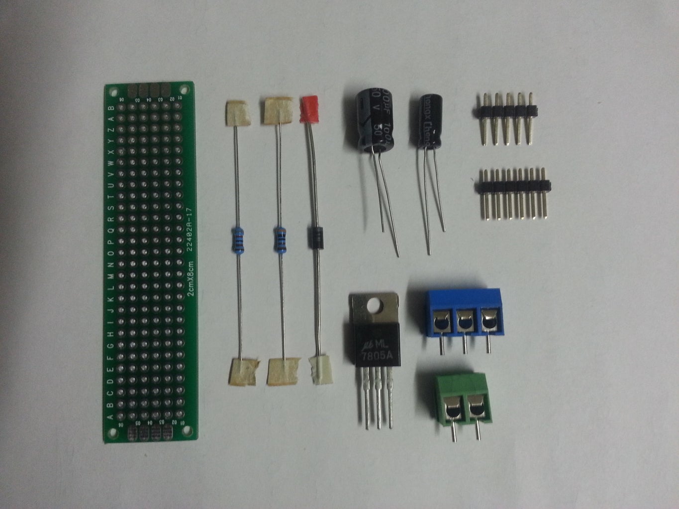
There is not alot of different parts that you need to build this project. Here is what i used.
Arduino Uno
GPRS shield
Relay shield
Prepaid sim card
Two sided protoboard
1N4001 diode
8200 ohm resistor
3000 ohm resistor
100 uF condensator
33 uF condensator
LM7805 regulator
5-pin and 6-pin headers
3-pin terminal
2-pin terminal
and some wire.
Total cost of this project is about 40 - 50 euros depending where you buy all of this.
Step 2: Tools and Skills
This is fairly simple project and you need only some basic knowledge of soldering and how electronics and arduino works.
As for the tools:
soldering iron
soldering tin
wire cutters
a small drill
multimeter to set the correction value for the analog voltage measurement
Step 3: Schematic


The schematic for this project is fairly simple. I do recommend to use a little bit bigger protoboard. You can use different resistor values or different diode.
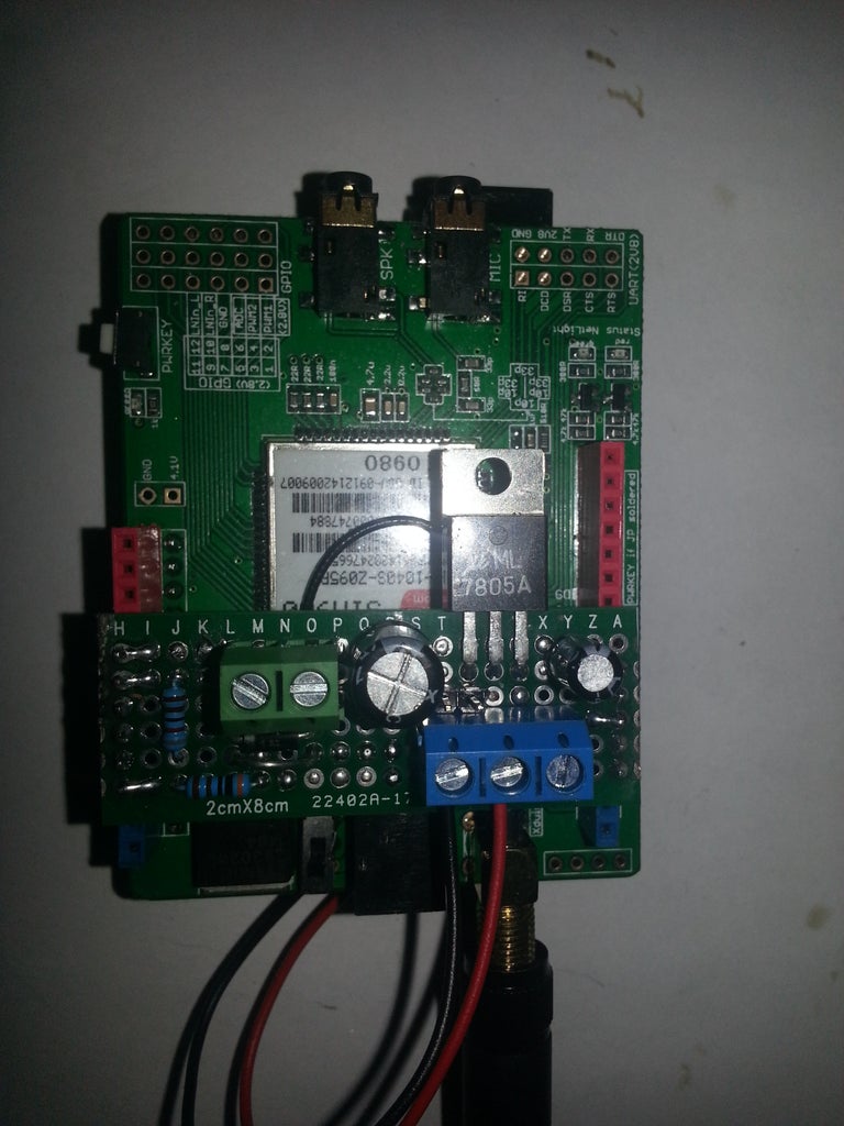
Step 4: Modify the GPRS Shield
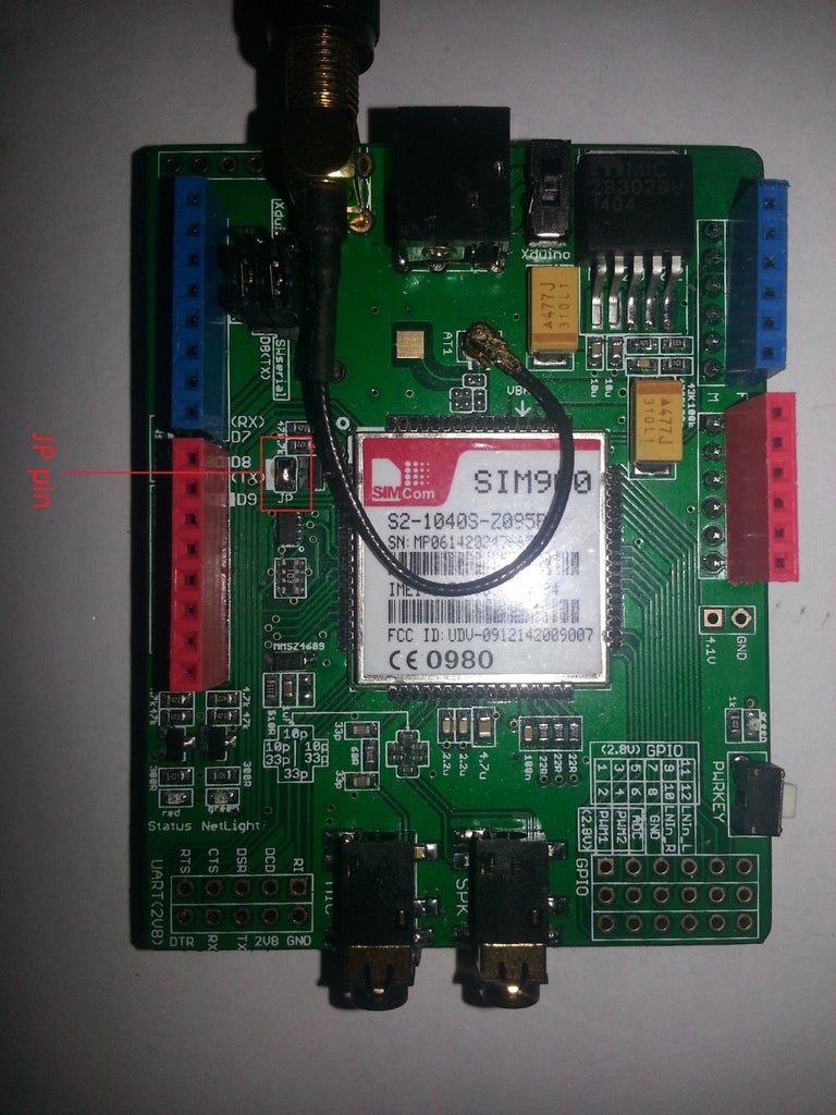

I modified the GPRS shield a bit to make it possible to power it on by using software and not the power button, by soldering se JP pin on the shield. I also soldered wires to the power connector so I can make the enclosure a bit smaller.
I read somewhere that the GPRS shield can take up to 2 A surge currents, I'm not sure if this is true. So for that reason I decided to power it externally. There is a small switch near the antenna which lets you choose how you want to power the GPRS shield.
Step 5: Modify the Oval Clock From Webasto
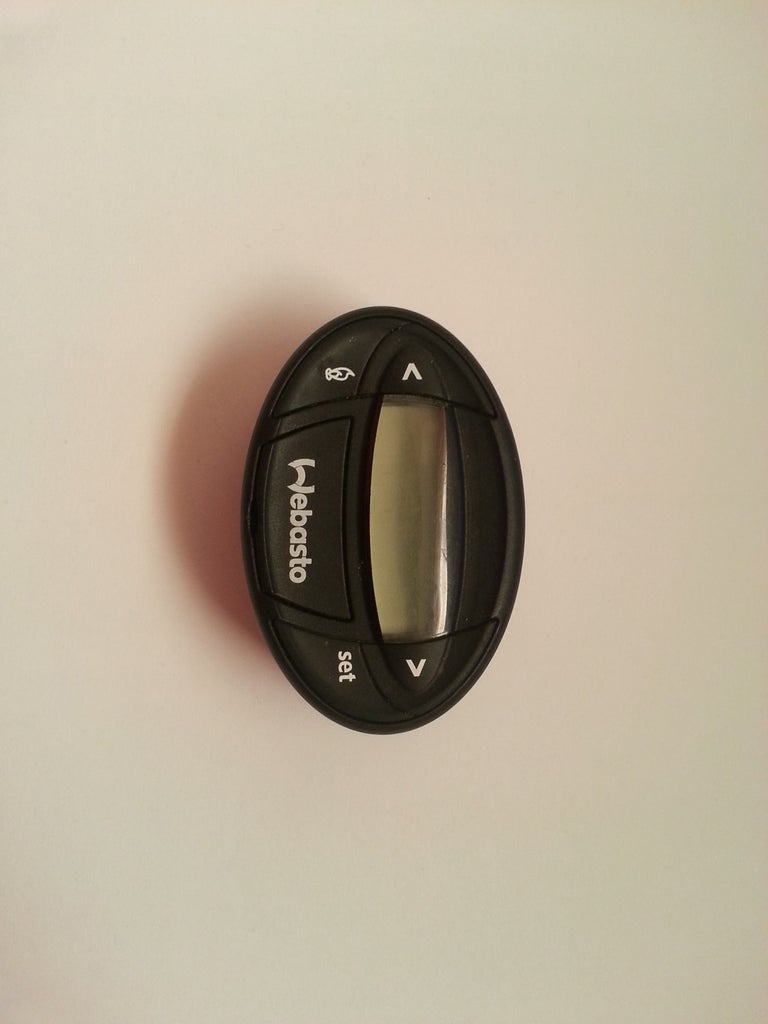
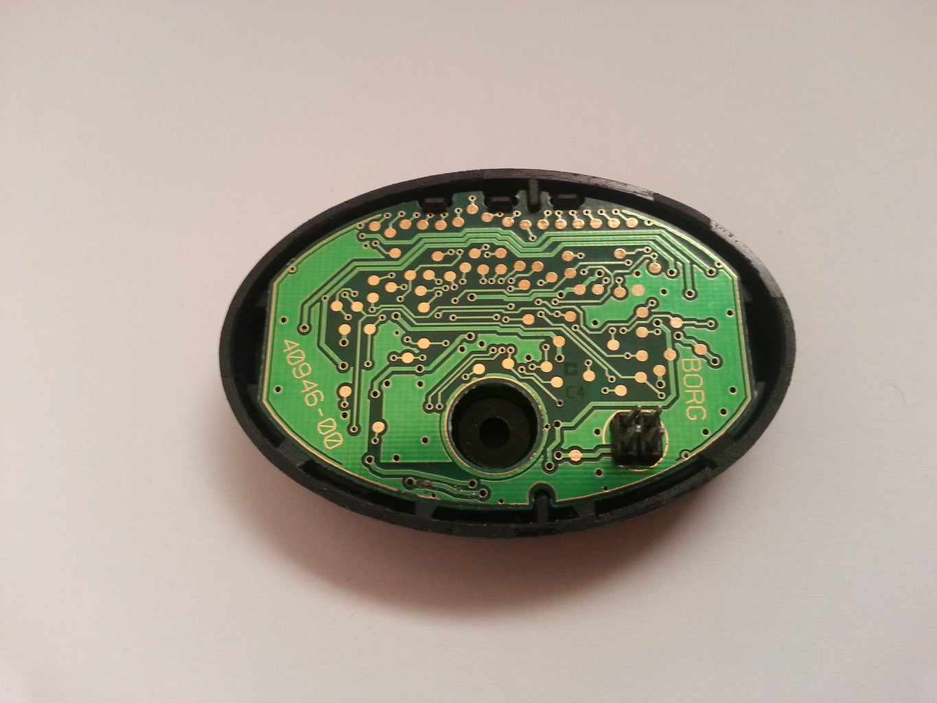

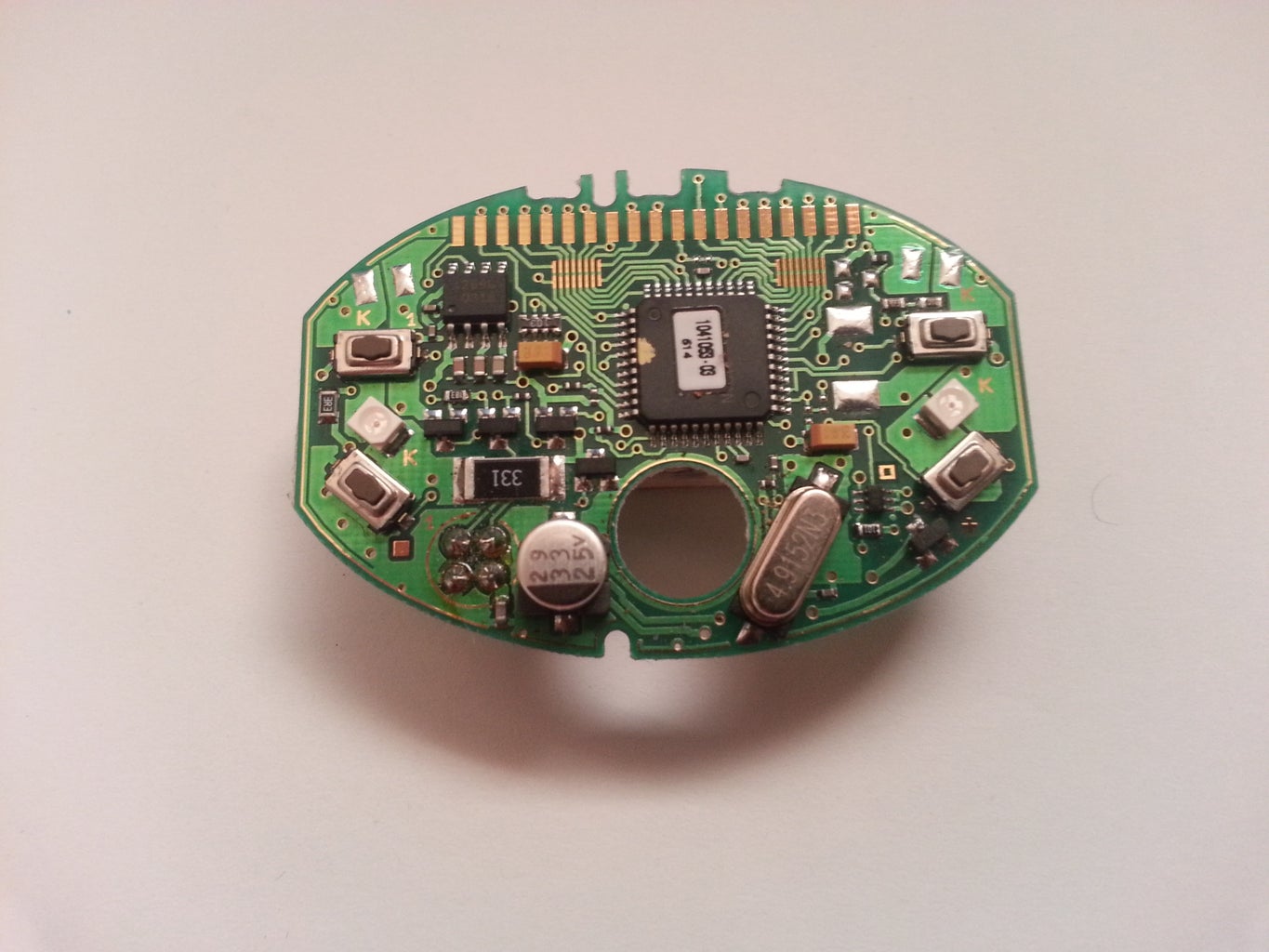
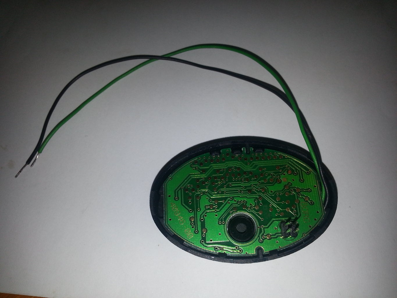

With the webasto clock removed, pry the back of the clock. At this point you should see the circuit board. VERY carefully pry the circuit board of too. The display might come too or stay in the plastic case, you dont need to worry about breaking it if it stays in the plastic case.
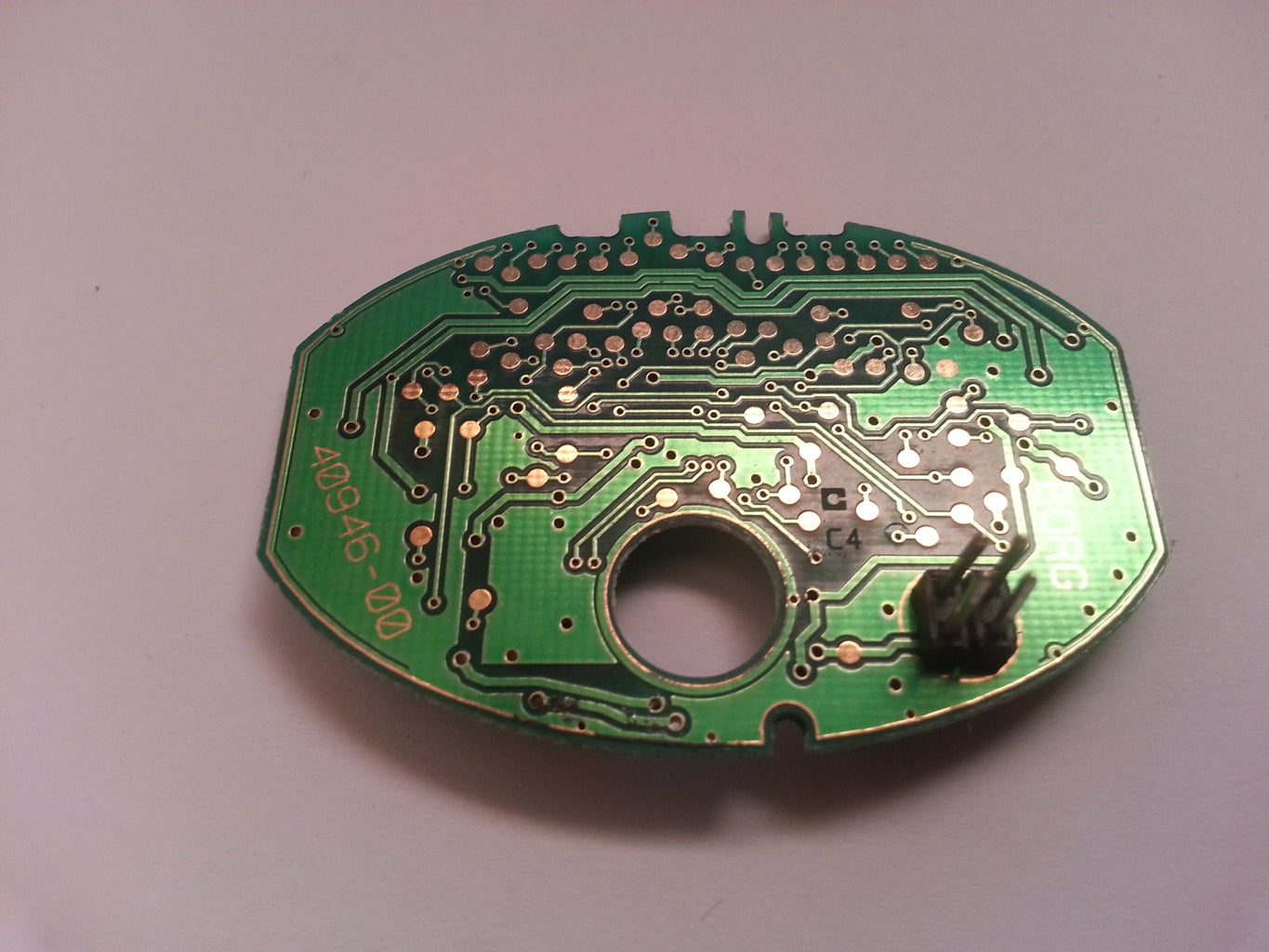
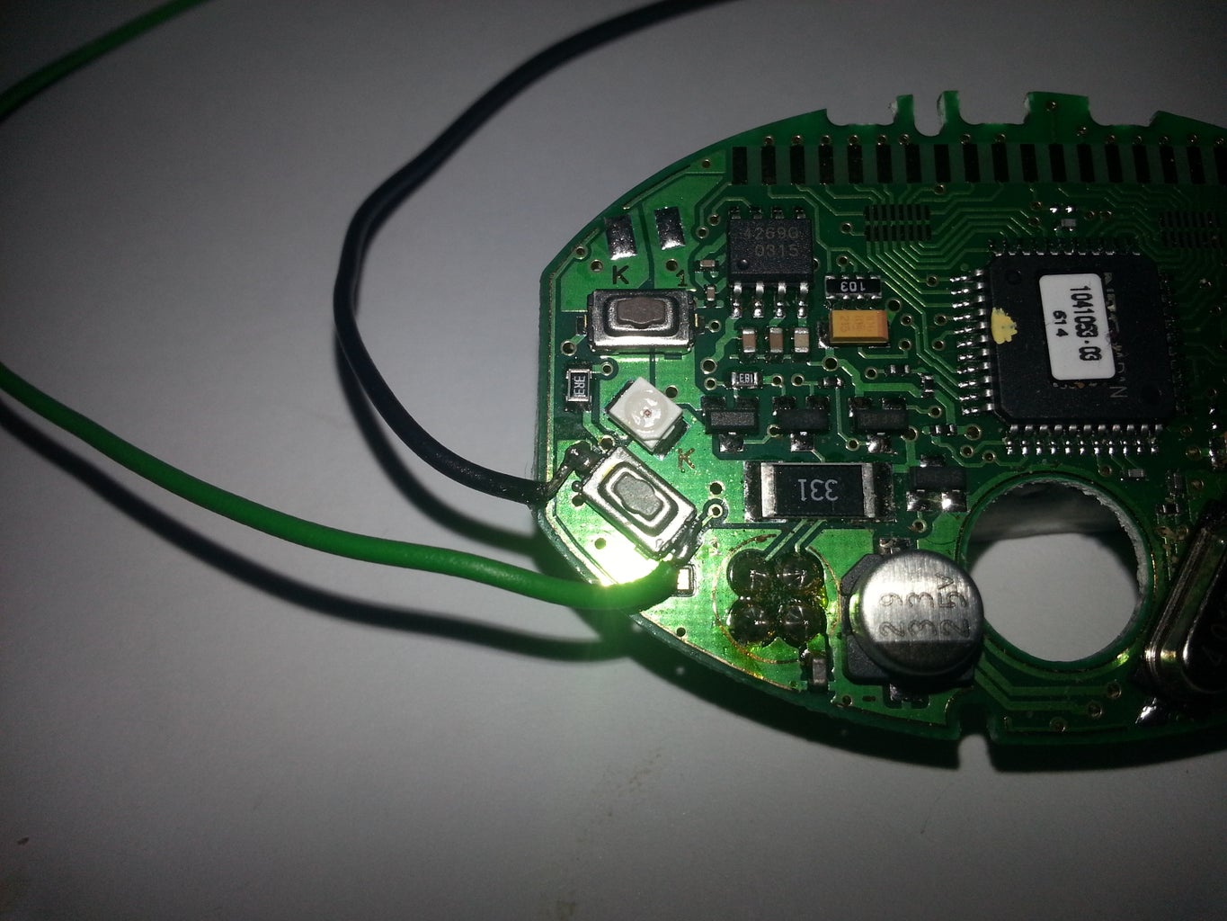
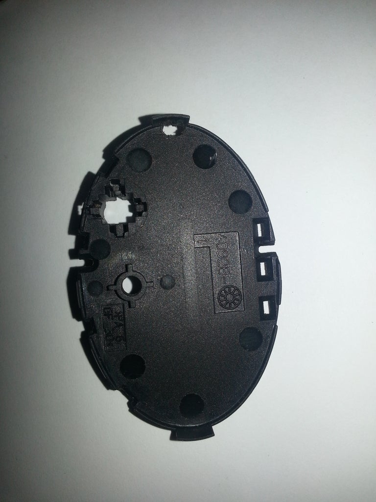
You need to solder two wires to the "flame" pushbutton. You also need to drill a small hole in the back cover for the two wires.
Step 6: Software
There are few features on the software you might want to change if you use this to contol something else. There is minimum voltage limits for the webasto and power down mode for the GPRS shield. If the battery voltage goes under these values the webasto won't be turned on and if it goes under the power down value the GPRS shield will be shut down. When the battery voltage goes over the value the GPRS shield will be powered back on and the webasto can be started.
You can add multiple phone numbers to this project that can control the relay, just separate them by using comma, and only these added phone numbers can control this device. The phone number format this software uses is the international format without the + sign. So if my phone number were 0401111111 and the country code to Finland is +358 the international format would be +358401111111. So in the software I would use as my number 358401111111. You also need to set the phone number length, mine would be 12. There is also a alarm phone number in the software. Once the voltage goes under the power down voltage limit a text message is sent to that alarm phone number before powering down the GPRS shield.
There is also a correctionValue variable in the software which you might need to adjust a bit depending on the value of your resistors.
I have tried to comment the source code so people can understand what is happening there.
Attachments

Step 7: Put It All Together
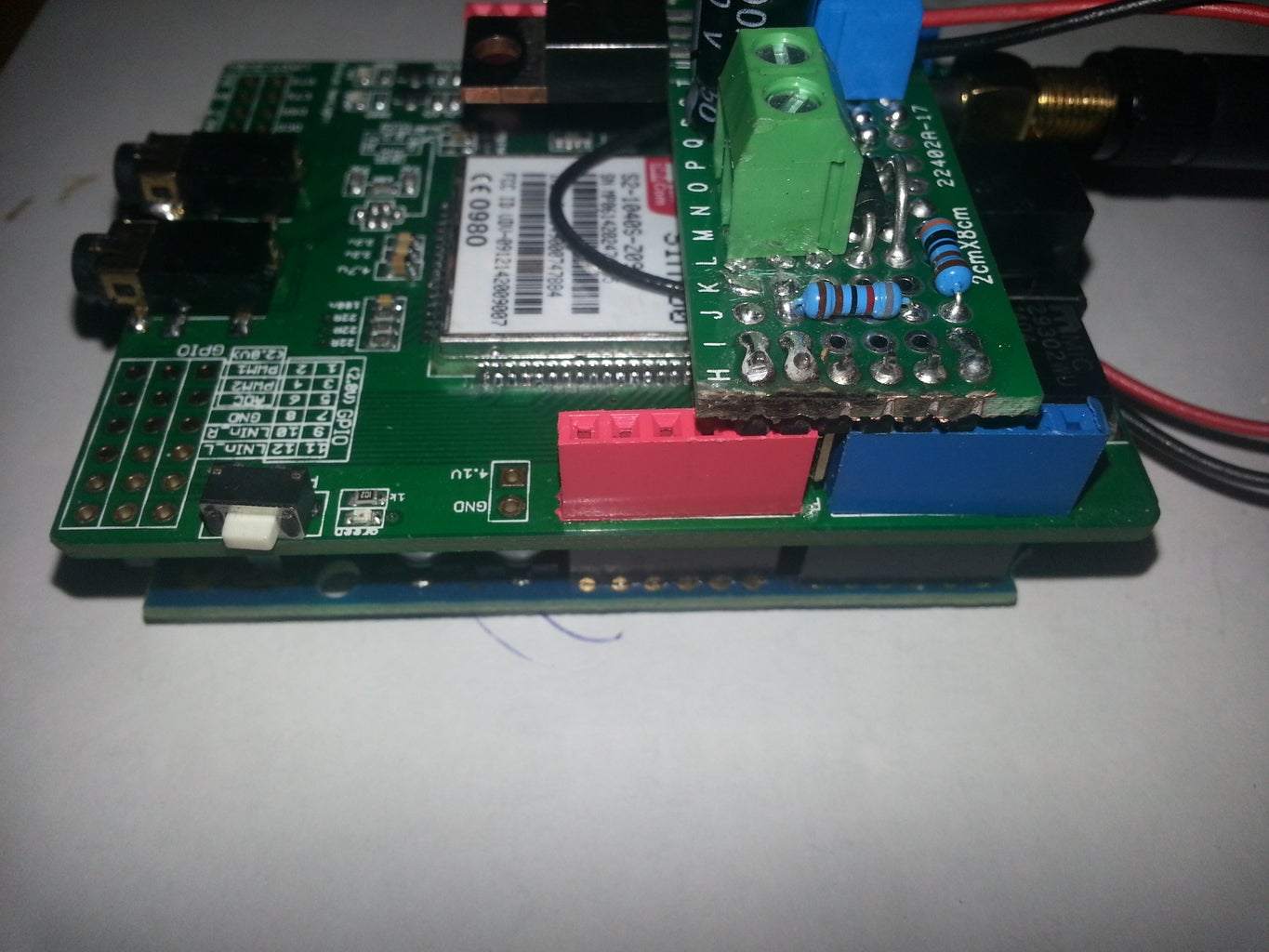
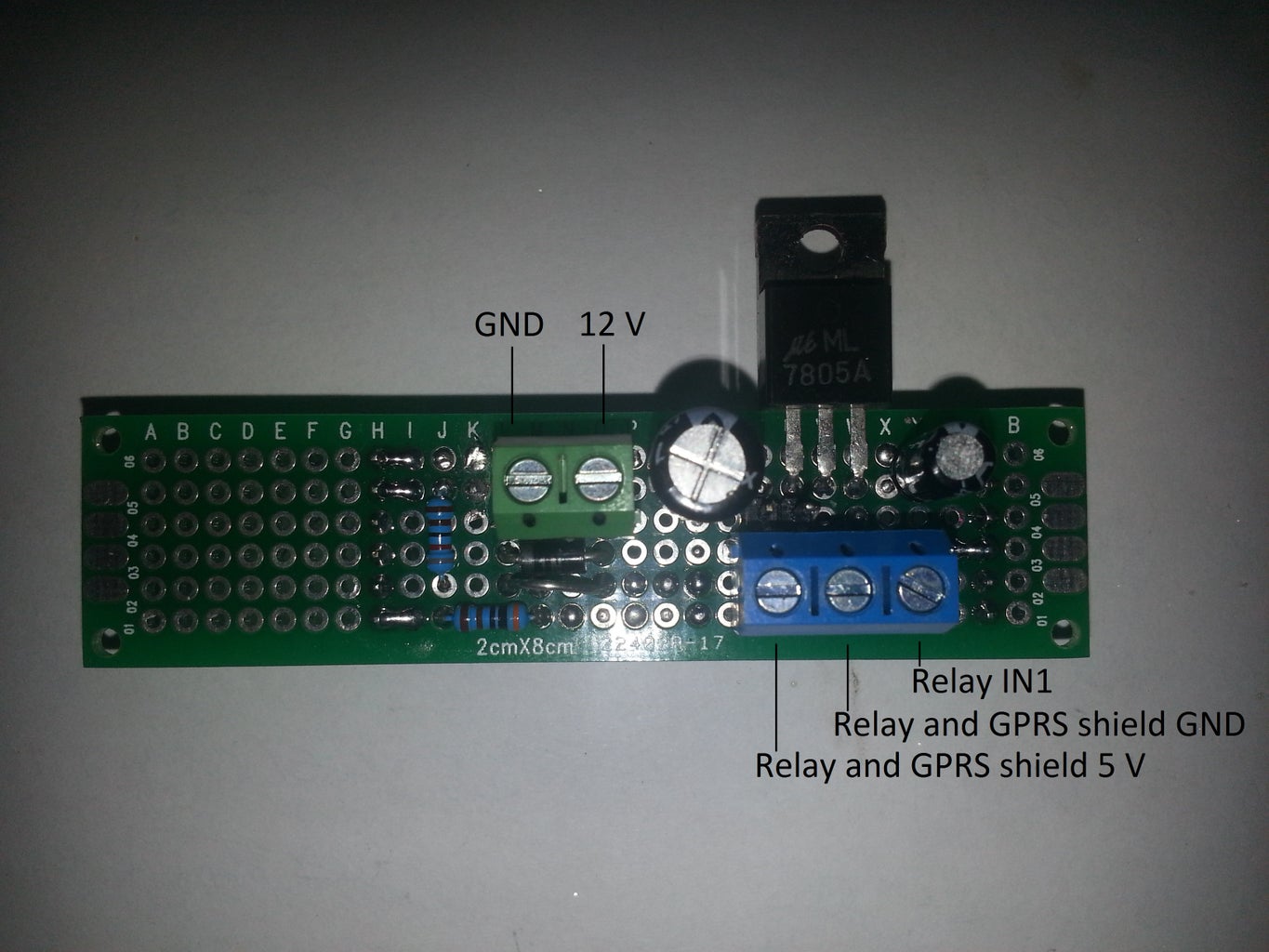
Just put the GPRS shield on top of the UNO and the protoboard on top of the GPRS shield. Hook up the wires from the GPRS shield and relay shield to the power terminal,in my case the blue one. And the IN1 from relay to the arduino digital 5, or in my case also to the blue terminal. If you build the protoboard the same way than me you only need to provide power, 12 volts, to the green terminal, it will also power the arduino by using the Vin pin. Hook the wires from the clock to the NC and COM terminal on the relay. And your done.
Next thing is to test it. If it works make some enclosure and install it some where in the car that has GSM signal.
The maximum voltage is 19 volts to this device. after that the analog pin from arduino will break. So this will be able to handle the fact if you need to use a booster, 16.9 volts, to get your car started.

Participated in the
First Time Author Challenge


