

Introduction: Arduino-powered LED Clock


A fun, simple LED clock, that will give you the time to the nearest half hour using single-color LEDs. Parts needed are as follows:
- Arduino Nano
- 400 tie-point Breadboard
- Ribbon Cable
- DS1307 RTC IC
- 32.768 kHz Crystal
- (12) 10mm LEDs
- (12) 180 Ohm resistors
- (2) 10k Ohm resistors
- 0.1" spaced, 12 wire ribbon cable, 7" long
- Jumper wires
- 18" x 6" 1/8" acrylic
The tools needed for this job are:
- Laser Cutter
- Soldering iron, flux, solder
- Wire cutter
- Wire stripper
- Needle-nose pliers
- Vice (optional)
- Hot glue gun
- Arduino IDE installed on a computer
Step 1: Laser-cut Clock Casing


The first thing that needs to be done for this LED clock is to design the clock case! This gives the layout of your LEDs as well as a good housing to use to help keep the assembly very neat and simple. I attached my illustrator file that can be used on a laser cutter with 1/8" acrylic and is designed to snap together.
Attachments

Step 2: Place LEDs in Holes

The easiest way I have found to assemble this clock is as follows:
- Clamp the clock face in a vice and angle it so the engraved side faces downward
- Drop the 10 mm LEDs in the back of the clock in each of the 12 holes
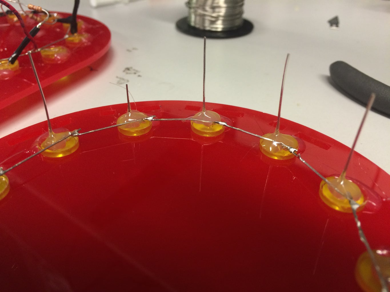
Step 3: Solder a Common Anode


Once your LEDs are in the holes, you should notice that on each LED, one lead is longer than the other. The longer of the two leads is called the anode. The laser file was designed with the holes far enough apart that if the anode of each LED is bent to be horizontal, it can reach out to make contact with the anode of the next LED when it is horizontal as well. Bend all of the anodes 90 degrees and lay them out in a circle with all of the anodes touching each other. These leads can now be soldered together, but making sure not to touch these to the cathodes when they are soldered! To solder them, first apply a bit of flux to the joint you are soldering and wet the tip of your iron by melting solder onto it and then scrubbing it off on a brass sponge. Apply the iron to the joint being soldered and then put solder to the joint. The solder will melt and when enough has been applied, remove the solder, and then remove the iron, and the joint should cool and harden.
Step 4: Hot Glue


Once these have all been soldered, apply some hot glue on the bottom of each LED. This should keep the two lead from shorting and should also help prevent the leads from breaking at the base of the light from stress. Once this is done, you can apply a little hot glue to fillet the acrylic with the side of the LEDs to keep them from falling out.
Step 5: Add Current-limiting Resistors


We will now be soldering a current-limiting resistor to the cathode of each LED so that we don't burn out the LEDs when we run our clock! With the wire cutter, snip the cathode to about 3/8" and do the same to both sides of the resistor leads. Hold one lead of the resistor with the needle-nose pliers and solder the other lead to the cathode. Do this for all 12 LEDs.
Step 6: Solder on a Ribbon Cable

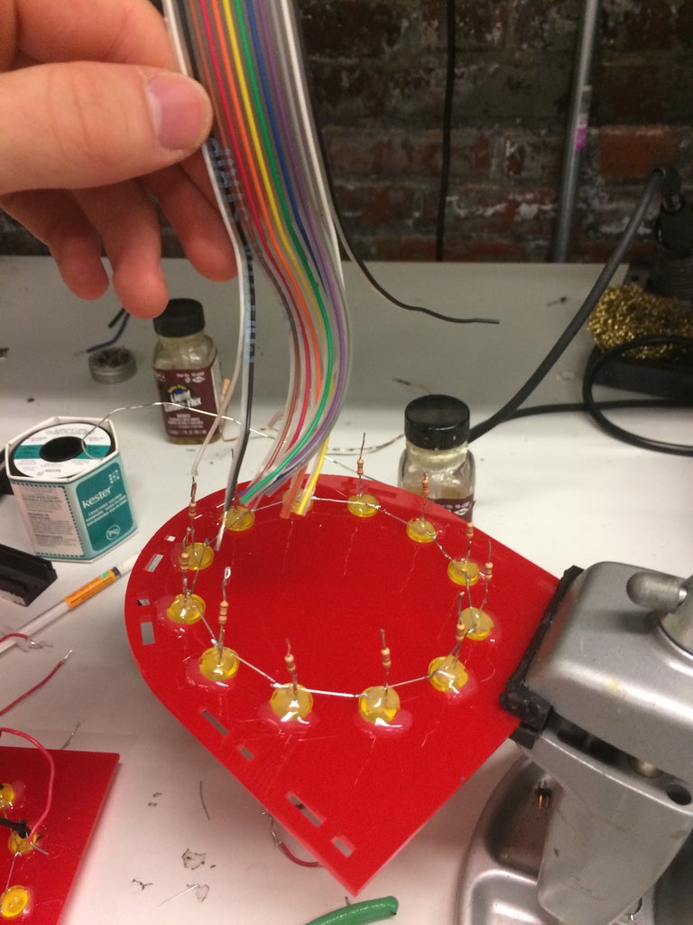


Take your 7-inch ribbon cable and separate the wires apart to about halfway down the cable. Strip both ends of the cable as well, exposing about 1/4" on each side. Starting at the LED for 1:00, solder the first wire in the ribbon cable, and follow all the way around the clock with the second wire at 2:00, third wire at 3:00, and so on. Once all the separated wires are soldered, we can take a look at the other end. Separate just the wire connected to 1:00 from the rest of the wires and solder a single pin header to it. Then take the remaining 11 headers and solder them to the 11 exposed wires on the ribbon cable.
Step 7: Attach a Wire to the Common Anode

Here we can just take a jumper wire or any wire that is solid-core and solder it anywhere along the common anode.
Step 8: Set Up Breadboard


- Place the Arduino on the breadboard with the Micro-USB port facing out of the board
- Set up the RTC circuit
- Connect pin 1 of the RTC to pin 2 of the RTC with the crystal (non-polarized, so direction doesn't matter)
- Connect pin 3 of RTC to positive terminal of the battery
- Connect pin 4 of RTC to negative terminal of battery and ground
- Connect pin 5 (SDA) of RTC to pin A4 on the Arduino with a 10k resistor
- Connect pin 6 (SCL) of RTC to pin A5 on the Arduino with a 10k resistor
- Ignore pin 7 of RTC
- Connect pin 8 of RTC to the 5V pin on the Arduino
- Plug the wire from the common anode in the 5V pin on the Arduino
- Plug the ribbon cable into the Arduino pins 2-12
- Plug the stray wire from the 1:00 LED into pin 13 on the Arduino
- Connect ground to the ground pin on the Arduino
Step 9: Set Time on RTC
Once the wiring is all set, download these files and go to your Documents > Arduino > libraries and create a folder called DS1307RTC and place all these files in there. Now open Arduino and load the sketch "SetTime". Upload this to your arduino and check in the COM Port that it is printing the correct information.
Step 10: Upload Code to Arduino
Download the Clock code I uploaded and upload it to the Arduino. If everything is wired properly, it will be interpreting the time from the RTC and rounding to the nearest half hour and lighting up the appropriate LEDs. Now that this works, have fun playing with the code and see what else you can make it do! Try adding a minute hand that flashes as it goes around, or turn it into a kitchen timer! The possibilities are endless!
Step 11: Attach Sides and Back Plate


Using the pinch tabs on the side panels attach them to the face plate, with the hole lining up with the Micro-USB port. Grab a more permanent base if you'd like and stick the bottom of the breadboard down to it. Lastly, use the pinch tabs on the other side to attach the back plate, and you are good to go with your Arduino-powered LED clock!


