

Introduction: Arduino Powered Three Color 8x8 Led Array

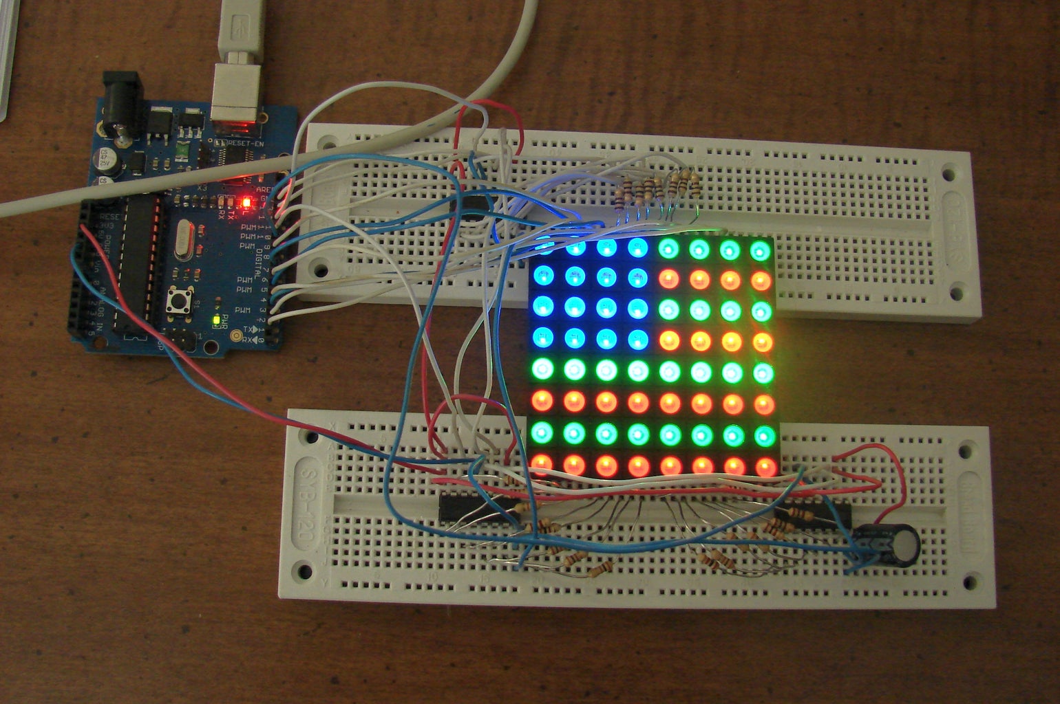
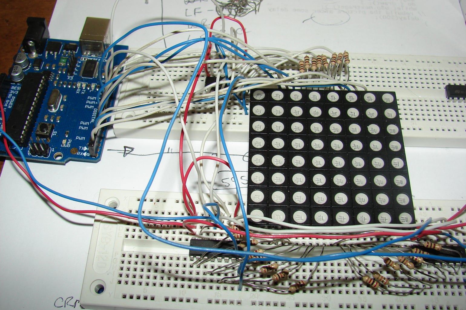


How to connect a three color, as in red, green and blue, 8 column by 8 row LED array to an Arduino. The model number of the array in use is CRM-2388ARGB-L. It did not come with any wiring instructions, so I set down with a 9 volt battery and a 1K resistor and figured out how it is wired up.
There are two rows of 16 pins each. The top row does not have the part number near it. The bottom row, left most pin, is the closest pin to the part number. There is also a letter “1” near this pin. This is what I found the pinout to be.
-----Rows------ ---------------Green----------------- ------Rows-----
R8 R7 R6 R5 G1 G2 G3 G4 G5 G6 G7 G8 R4 R3 R2 R1
32 31 30 29 28 27 26 25 24 23 22 21 20 19 18 17
-------------------------------------------------------------------------------
0 0 0 0 0 0 0 0
0 0 0 0 0 0 0 0
0 0 0 0 0 0 0 0
0 0 0 0 0 0 0 0
0 0 0 0 0 0 0 0
0 0 0 0 0 0 0 0
0 0 0 0 0 0 0 0
0 0 0 0 0 0 0 0
-------------------------------------------------------------------------------
1 2 3 4 5 6 7 8 9 10 11 12 13 14 15 16
B1 B2 B3 B4 B5 B6 B7 B8 R1 R2 R3 R4 R5 R6 R7 R8
---------------Blue----------------- ----------------Red-----------------
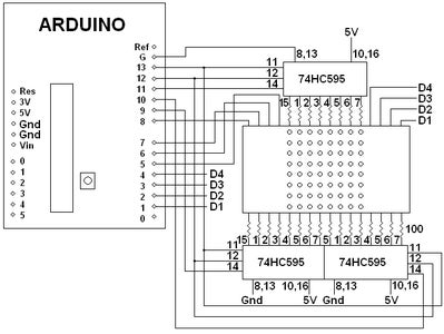
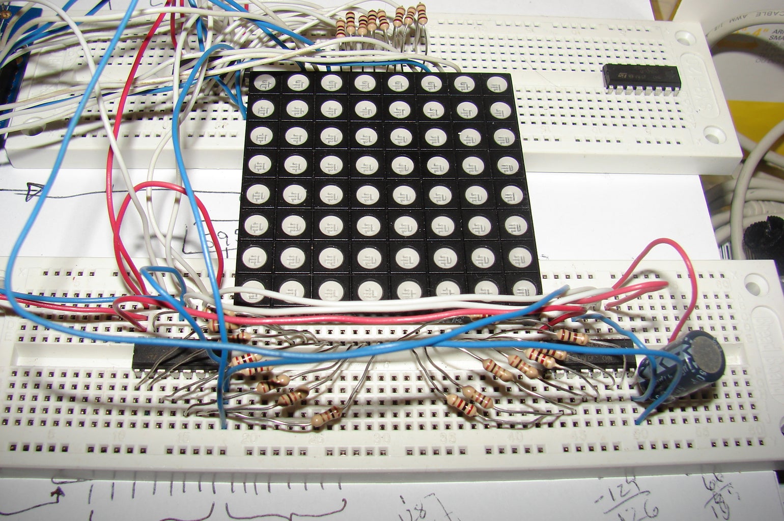
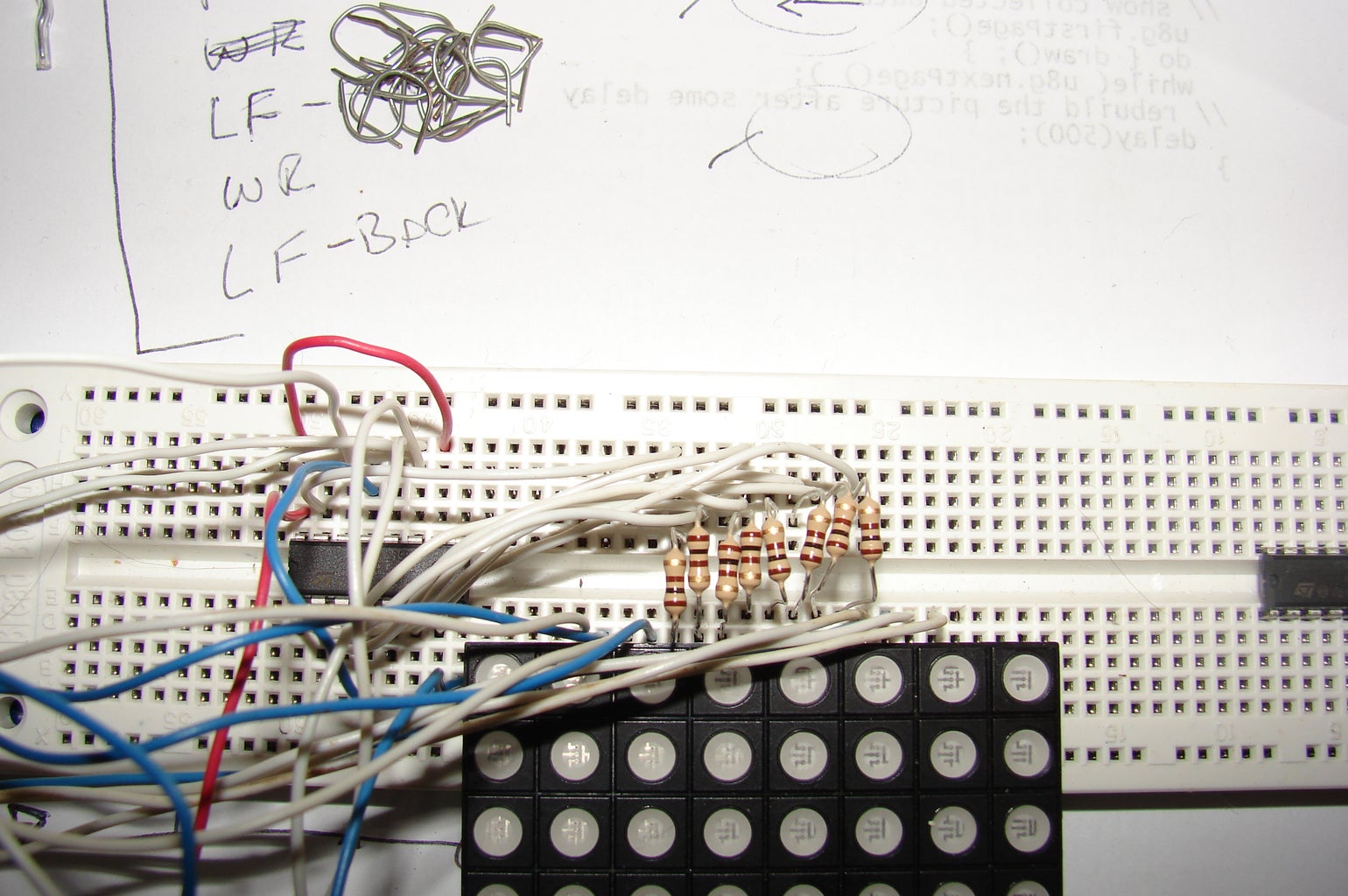
Once it is set up on two breadboards I wired up three 74HC595 shift registers with eight 100 ohm resistors each to the red, green and blue array pins. I was reusing a design that had previously worked for a two color 8 by 8 led array.
For the rows there should have been some row driver transistors, but I directly connected the rows to pins D1-D8 of the Arduino and it worked. You might get a little more brightness with row driver transistors.
Step 1: The Arduino Sketch to Make It Work.
Here is the code for the Arduino:
//********************************************/
// Name : LED 8x8 RGB SR array Driver
// Author : Bob Davis
// Date : 2 January, 2014
// Version : 1.0
//********************************************/
// Assign Pins for the shift registers and Rows
int Row1 = 1;
int Row2 = 2;
int Row3 = 3;
int Row4 = 4;
int Row5 = 5;
int Row6 = 6;
int Row7 = 7;
int Row8 = 8;
int RSerial = 9;
int BSerial = 10;
int GSerial = 11;
int RCLK = 12;
int SCLK = 13;
// Set up arrays, select one of these three things to display
// RGB Flag
//byte Bbitmap [8]={240, 240, 240, 240, 0, 0, 0, 0};
//byte Gbitmap [8]={15, 0, 15, 0, 255, 0, 255, 0};
//byte Rbitmap [8]={0, 15, 0, 15, 0, 255, 0, 255};
// Blue Face
byte Bbitmap [8]={60, 126, 255, 219, 255, 219, 102, 60};
byte Gbitmap [8]={60, 126, 129, 165, 129, 129, 0, 0};
byte Rbitmap [8]={60, 126, 0, 36, 0, 36, 24, 0};
// Red Car
//byte Gbitmap [8]={8, 0, 0, 0, 0, 0, 255, 255};
//byte Bbitmap [8]={255, 255, 255, 131, 0, 0, 0, 0};
//byte Rbitmap [8]={8, 0, 0, 124, 255, 189, 0, 0};
// Set the pins to output to the array
void setup() {
pinMode(Row1, OUTPUT);
pinMode(Row2, OUTPUT);
pinMode(Row3, OUTPUT);
pinMode(Row4, OUTPUT);
pinMode(Row5, OUTPUT);
pinMode(Row6, OUTPUT);
pinMode(Row7, OUTPUT);
pinMode(Row8, OUTPUT);
pinMode(BSerial, OUTPUT);
pinMode(GSerial, OUTPUT);
pinMode(RSerial, OUTPUT);
pinMode(RCLK, OUTPUT);
pinMode(SCLK, OUTPUT);
}
void loop() {
for (int row = 0; row <8; row++){
//turn everything off
digitalWrite (Row1, LOW);
digitalWrite (Row2, LOW);
digitalWrite (Row3, LOW);
digitalWrite (Row4, LOW);
digitalWrite (Row5, LOW);
digitalWrite (Row6, LOW);
digitalWrite (Row7, LOW);
digitalWrite (Row8, LOW);
// set up the data in the shift registers
for (int shiftbit = 0; shiftbit <8; shiftbit++){
digitalWrite(BSerial, HIGH);
digitalWrite(GSerial, HIGH);
digitalWrite(RSerial, HIGH);
if bitRead(Bbitmap[row],shiftbit) digitalWrite(BSerial, LOW);
if bitRead(Gbitmap[row],shiftbit) digitalWrite(GSerial, LOW);
if bitRead(Rbitmap[row],shiftbit) digitalWrite(RSerial, LOW);
digitalWrite(SCLK, LOW);
digitalWrite(SCLK, HIGH);
}
//latch the data
digitalWrite(RCLK, HIGH);
digitalWrite(RCLK, LOW);
// turn on the associated row
if (row == 0) digitalWrite (Row1, HIGH);
if (row == 1) digitalWrite (Row2, HIGH);
if (row == 2) digitalWrite (Row3, HIGH);
if (row == 3) digitalWrite (Row4, HIGH);
if (row == 4) digitalWrite (Row5, HIGH);
if (row == 5) digitalWrite (Row6, HIGH);
if (row == 6) digitalWrite (Row7, HIGH);
if (row == 7) digitalWrite (Row8, HIGH);
delay(2);
} }

Participated in the
Arduino Contest


