

Introduction: Arduino Powered Bluetooth Remote Relay Switch


Hi
I wanted to build a simple 2 channel bluetooth remote switch box.
to allow me to remotely switch various devices on and off from my android phone.
The device had to be small easy to use and flexable enough to control anything I wanted.
some of the uses are controling my slr camera. and to switch on mains devices like lights.
parts needed.
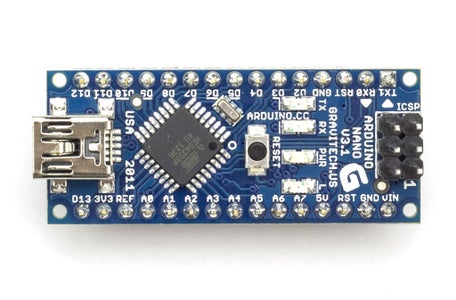
1 arduino board ( i used a arduino nano as it was small and easy to attach to a computer to program)
1 relay board
1 bluetooth module (I used a jy-mcu module because it was cheap)
A plastic box to put everything in
A battery holder
I purchased the arduino board the bluetooth module and the relay board from ebay.
the plastic box and battery holder came from maplin.
be careful when purchasing the bluetooth module and check that its the board and bluetooth chip. as some on ebay are just the board without the bluetooth chip.
total cost was £20
Step 1: Connecting the Arduino Board to the Computer
first of all I connected the arduino board to my computer usb port.
the board should light up.
now if you havnt got the arduino IDE software you should go here http://arduino.cc/en/Main/Softwareto download it
it should already be in the repositorys if you are using ubuntu linux.
when the software has been installed and opened. check the port and board setting are correct.
this will be under tools > board (select the board option to match your arduino board)
and tools > serial port. if this is greyed out you will have to check that your drivers are installed correctly for your board.
when the software is set up and communicating with your arduino. its time to write the code.
Step 2: Arduino Sketch

here is a copy of my arduino sketch.
what will happen is when I send a command A to H the relay will be switched on and if I send a to h the relay will be switched off.
I have programmed it so that
A is relay one on (latched)
B is relay two on (latched)
C is relay one on for 1 second
D is relay two on for 1 second
E is relay one on for 5 second
F is relay two on for 5 seconds
G is relay one on for 1 second then relay two on then both off
H will switch relay one on and off for 1000 times
the relays switch on when the digital pin is grounded. and the relay switches off when the digital pin goes high
here is the code
/*
simple LED test
*/
char val; // variable to receive data from the serial port
int ledpin = 2; // LED connected to pin 2 (on-board LED)
void setup()
{
pinMode(ledpin = 2, OUTPUT); // pin 2 (on-board LED) as OUTPUT
pinMode(ledpin = 3, OUTPUT); // pin 3 (on-board LED) as OUTPUT
Serial.begin(9600); // start serial communication at 115200bps
}
void loop()
{
if( Serial.available() ) // if data is available to read
{
;
}
val = Serial.read(); // read it and store it in 'val'
if( val == 'a' ) // if 'a' was received led 2 is switched off
{
digitalWrite(ledpin = 2, HIGH); // turn Off pin 2
}
if( val == 'A' ) // if 'A' was received led 2 on
{
digitalWrite(ledpin = 2, LOW); // turn ON pin 2
}
if( val == 'b' ) // if 'b' was received led 3 is switched off
{
digitalWrite(ledpin = 3, HIGH); // turn Off pin 3
}
if( val == 'B' ) // if 'B' was received led 3 on
{
digitalWrite(ledpin = 3, LOW); // turn ON pin 3
} //else (ledpin = 3, LOW) //set led pin 3 to low state
if( val == 'C' ) // if 'C' was received led 2 on for 1 second
{
digitalWrite(ledpin = 2, LOW); // turn ON pin 2
delay(1000); // wait 1 second
digitalWrite(ledpin, HIGH); // turn Off pin 2
}
if( val == 'D' ) // if 'D' was received led 3 on for 1 second
{
digitalWrite(ledpin = 3, LOW); // turn ON pin 3
delay(1000); // wait 1 second
digitalWrite(ledpin, HIGH); // turn Off pin 3
}
if( val == 'E' ) // if 'E' was received led 2 on for 5 seconds
{
digitalWrite(ledpin = 2, LOW); // turn ON pin 2
delay(5000); // wait 500 milli seconds
digitalWrite(ledpin, HIGH); // turn Off pin 2
}
if( val == 'F' ) // if 'F' was received led 3 on for 5 seconds
{
digitalWrite(ledpin = 3, LOW); // turn ON pin 3
delay(5000); // wait 500 milli seconds
digitalWrite(ledpin, HIGH); // turn Off pin 3
}
if( val == 'G' ) // if 'G' was received turn led pin 2 on for 500ms then switch off and turn on pin 3 for 500 mili seconds then off
{
digitalWrite(ledpin = 2, LOW); // turn ON pin 2
delay(500); // wait 500mili second
digitalWrite(ledpin, HIGH); // turn Off pin 2
digitalWrite(ledpin = 3, LOW); // turn ON pin 2
delay(500); // wait 500 mili second
digitalWrite(ledpin, HIGH); // turn Off pin 2
}
if( val == 'h' ) // if 'h' was received switch off all pins
{
digitalWrite(ledpin = 13, LOW); // turn Off pin 13
digitalWrite(ledpin = 2, HIGH); // turn Off pin 2
digitalWrite(ledpin = 3, HIGH); // turn Off pin 3
}
if( val == 'H' ) // if 'H' was received switch pin 2 on and off 1000 times
for(int i = 0; i < 1000; i++)
{
digitalWrite(ledpin = 2, HIGH); // turn ON pin 2
delay (1000); //wait 1000 mili seconds
digitalWrite(ledpin = 2, LOW); // turn Off pin 2
delay (1000); //wait 1000 mili seconds
}
}
Step 3: Uploading the Code
when you are happy with the sketch it can be uploaded to the arduino by pressing the upload button in the IDE.
you will not be able to upload the code if the bluetooth module is already connected to the arduino.
Step 4: Wiring It All Together.
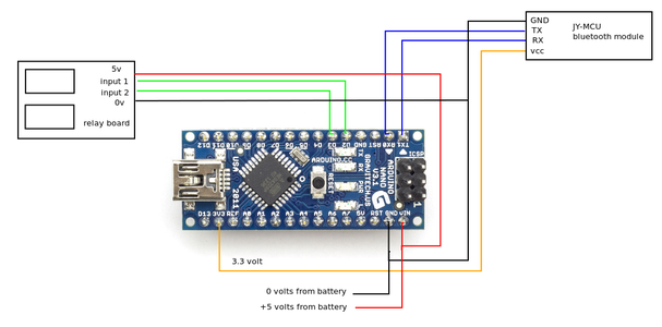

the relay board and arduino will need a 5volt power supply.
the bluetooth module can be powered from the 3.3 volt pin on the arduino.
the tx on the bluetooth board will be connected to the rx pin on the arduino
the rx pin on the bluetooth board will be connected to the tx pin on the arduino
and the digital output pins 2 and 3 on the arduino will be wired to the relay board as shown in the diagram.
Step 5: Connecting to Your Phone and Testing


now if you have uploaded the code ok.
and everything is wired correctly the boards should power on and the light on the bluetooth module should flash.
I wanted to be able to control it from my android phone.
luckly for me Amphan had already done all the hard work and writen a very good android app called Arduino Bluetooth Control. which is on the google play store
https://play.google.com/store/apps/details?id=com.app.control&hl=en
after installing and opening the arduino bluetooth control app. I had to pair the phone to the bluetooth module.
my module was listed as HC-06 and the pin was 1234.
after pairing it was just a matter of pressing the connect button on the bottom of the app.
they connected ok and I was able to switch the relays on and off using the buttons on the app.
if you have problems connecting or controlling the arduino check that the baud rate in the software matches the baud rate of the bluetooth module.
Step 6: Fitting Everthing in the Box
the next step was to mount everthing in a plastic box.
the box i got from maplin was quite small and the battery holder just fitted after a little alteration.
I had to cut a few holes and drill some mounting holes for the relay board.
and here is the finished device.
after checking that it all still worked propperly.
I wired up a light to the relay to check that it all switched as required.


