

Introduction: Arduino Text LCD Animation
I've seen many pages about how to wire up an LCD panel to an Arduino, and pages that help you draw custom characters, but I didn't see many that used the custom character function for animation.
What you'll need for this:
- Arduino Uno
- HD44780-compatible LCD
- Solderless breadboard (prototyping breadboard)
- One 10K ohm resistor
- One 10K ohm potentiometer
- Soldering iron and soldering materials
Optional parts, if you solder your LCD to a separate board:
- Another small breadboard with at least two rows and sixteen holes per row (optional)
- A 16-pin female header or something similar (chip sockets, for example)
Even if you don't solder your LCD to a separate board, you'll probably need a 16-pin row of male-male headers so you can stick your LCD directly into a solderless breadboard.
Why do this little bit of hackery? There's no great utility in doing things this way for general pixel animation purposes. For that, you need a real LCD display, not a basic text display. However, the overall technique might be of interest to those with limited display componentry, and a need for some kind of animated progress or level indicator.
Step 1: Wire the LCD to the Breadboard

You can find other Instructables that explain how to do this step, which is to the first step for connecting the LCD panel to your Arduino. Before you can do that, you have to have some wires or headers stuck to your LCD panel's pin holes.
I was fortunate enough to find an LCD connected to a breadboard that someone else had used, apparently as their own soldering project. (I got it at the Tech Shop, Menlo Park / mid-Peninsula, in the donation bins!) It was a chunky little thing with two rows of seven pins on one end, and wires to "RA" and "RK" on the other end. Other panels are out there that have all the pins in one row, and they're much easier to connect to a solderless breadboard. But for mine, it already had wires connected to it, and those wires were too thin to stay in a solderless breadboard properly, so I chose to disconnect it from its old board, and solder its wires to my own breadboard, and then connect that to a solderless breadboard.
I cut the wires that connected the LCD to the old board, preserving as much connected wire as possible. Then, I cut all the wires so that they were roughly the same length. After that, I stripped the wires for through-hole soldering.
If you look on the back of the panel, you'll see that there are numbers indicating pins 1, 2, 13, and 14, so it was clear where each pin was. If you're wiring one of these on your own, I highly recommend using wires of different colors so you don't get things mixed up. The first time I did this, I reverse every pair of wires starting with wire 3, and had to undo and redo nearly everything.
I gently bent the wires and inserted the bare pins into the board. I did all the odd-numbered wires first, inserting all of them into their holes, and soldered pins 1 and 13 only to keep things in place. Then, I inserted all the even-numbered wires, and soldered 2 and 14. From there, everything was held in place well enough so that I could go down the line and solder each one in turn.
I then added the row of push-in headers. In my case, there were many more than sixteen holes, so I chose to leave the first empty, and just solder it and the last pin, simply to anchor the whole black bar to the board. I then soldered each of the pins to the breadboard.
Finally, I bent each of the blue wire tips towards its corresponding header pin, and I added solder bridges between each pair.
After that, I tested each pair of headers for connectivity to make sure I hadn't made any mistakes. I couldn't test the full connection from the header to the actual LCD pin very easily, so I had to trust that that had been done properly.
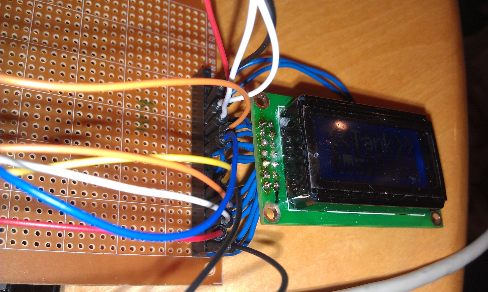
Step 2: Circuit Wiring

At this point, you should have an LCD with pins can be connected easily to a solderless breadboard and a circuit on it. You'll find similar instructions to these on other web pages.
Do all of this wiring before you connect power to the Arduino! And check, and double-check, and triple-check the wires that are going to Vcc and Ground to make sure you got those in the right order. Short-circuits and backwards wiring might be able to fry your LCD panel, plus it can fry pins and damage the Arduino. There are no resistors in this circuit nor any diodes to prevent bad things from happening. So please be careful! I can't be responsible if you wire it up wrong, or you use the wrong LCD panel for this.
The typical 44780 circuit connects pins in this order
LCD 1 = Ground
LCD 2 = Vcc (+5V)
LCD 3 = contract -- connect to middle pin of potentiometer; connect one side of pot to ground, and other through 10k resistor to Vcc.
LCD 4 = Reset = Arduino 7
LCD 5 = Read/write = tie to ground, since I'm only doing writes, no reads
LCD 6 = Enable = Arduino 8
LCD 7 through 14 = data lines DB0..DB7, respectively. I'm only interested in the last four bits, so connect
LCD 11 to Arduino 9
LCD 12 to Arduino 10
LCD 13 to Arduino 11
LCD 14 to Arduino 12
Because of these settings, the sketch code has to initialize the LiquidCrystal object using
LiquidCrystal lcd(7, 8, 9, 10, 11, 12);
// parameters, in order, represent pins for RS, EN, DB4, DB5, DB6, DB7
(In my attached image, you might notice that I wired the potentiometer incorrectly! I fixed that after I took the picture.)
You may use other pin assignments depending on your needs.
Step 3: Sketch the Thing You Will Animate

The HD44780 chip allows you to build and use up to eight custom characters, and the LiquidCrystal library lets you "create" a character. But the createChar(index, byteArray) function actually replaces the bits of the character definition, and if you have any drawn on the screen, the bits get updated immediately, so it's more like a "defineChar" call, or a "createOrUpdateChar" call.
For my animation, I wanted to draw a tank going across the screen. I chose to draw it as three characters on graph paper, and leave a fourth for bit shifting space. Since each character is 5 pixels wide by 8 pixels high, that gave me a 15x8 pixel area for sketching a tank.
In this initial drawing, you can see that I drew the treads, and drew "wheels" inside the treads, but I ended up ditching all that and using a single, solid tread outline for reasons you'll see later on.
Step 4: Building the Tank Bits in Code
I translated the tank drawing into long integers. Long ints give you 32 bits to play with, and so I could represent the tank using eight long ints, each one really only using 15 bits for the initial drawing.
The chunk of code for that is here. It's easier to read in a fixed-width font.
I could have defined these using hexadecimal values, but I figured using the Bnnnnnn binary notation would make it more readable.
// Need eight 32-bit quantities that I can use for shifting bits around.
// The original tank image is in these values.
long tankImg[] = {
((long)B010000 << 10) | ((long) B000000 << 5) | B000000 // antenna tip
,((long)B010111 << 10) | ((long) B011110 << 5) | B000000 // turret top
,((long)B001111 << 10) | ((long) B011111 << 5) | B011110 // turret mid with barrel
,((long)B000111 << 10) | ((long) B011110 << 5) | B000000 // turret base
,((long)B001111 << 10) | ((long) B011111 << 5) | B010000 // tread top
,((long)B010000 << 10) | ((long) B000000 << 5) | B001000
,((long)B010000 << 10) | ((long) B000000 << 5) | B001000
,((long)B001111 << 10) | ((long) B011111 << 5) | B010000 // tread bottom, 24 pixels total in tread
};
Step 5: Shifting Characters Across the Page
To move the tank, I defined a pixel-wise x position for drawing. Since I was dealing with characters that were five pixels wide, I could do an integer division of the tank x position to figure out the where I would draw each custom character.
I also would just take a modulo of the tank's x position (tankx % 5) to figure out how to shift the bits around. If the modulo was zero, I would draw the characters and define the bits of the characters. But if the modulo was non-zero, it meant the characters were already on the screen, and I could just redefine the bits. I also would draw a leading space to blank out any prior drawing of custom character 0 (the leftmost one) whenever I was "moving" the characters.
So, to start, I'd initialize the tankx position to some value that would divide cleanly by five.
int tankx = -15;
int tankcharx;
int tankchary = 1;
Then, within the loop() function, I'd do the division and the modulo to figure out what to draw, and how to draw. (Beware of how the modulo of negative numbers works.)
Another way to do this, in retrospect, would be to make tankx always non-negative, and shift the x character position by -3 before rendering.
This is the part of the loop() code that gets the custom characters onto the screen. In a better rendition of this code, I factored out the drawing functions into a safeDrawCharAt function that does the position check. But here you see the older rendition where I was doing the position checking inline. Since at any time the characters could be off screen, I had to do a position check before any setCursor() or write() calls.
tankcharx = tankx / BITS_PER_CHAR;
// Initial rendition, no rotation of treads
if ((tankx % BITS_PER_CHAR) == 0) {
// Full shift is on, need to draw a blank where the tank last was
if (tankcharx >= 1) {
lcd.setCursor(tankcharx-1, tankchary);
lcd.write(' ');
}
if (tankcharx >= 0 && tankcharx <= 7) {
lcd.setCursor(tankcharx, tankchary);
lcd.write((byte)0);
}
if (tankcharx+1 >= 0 && tankcharx+1 <= 7) {
lcd.setCursor(tankcharx+1, tankchary);
lcd.write((byte)1);
}
if (tankcharx+2 >= 0 && tankcharx+2 <= 7) {
lcd.setCursor(tankcharx+2, tankchary);
lcd.write((byte)2);
}
if (tankcharx+3 >= 0 && tankcharx+3 <= 7) {
lcd.setCursor(tankcharx+3, tankchary);
lcd.write((byte)3);
}
}
Step 6: Shifting the Tank Bits
With the characters now on the screen, you can modify their bits. Ultimately, you have to call the createChar(index, byteArray) function to get the bits to the LCD, and that means you have to have an eight byte array per character. I'm using four custom characters, so I used four byte arrays.
byte sprite0[8];
byte sprite1[8];
byte sprite2[8];
byte sprite3[8];
Within the loop(), I took the bitwise modulo position to come up with an offset. Then, I went a line at a time through the tank. Here, the efficiency of the long ints comes into play. First, I would copy the long int from the static tank drawing into a local variable. Then, I'd shift the whole long int back by the number of bits I'd need.
int shiftbits = (tankx % BITS_PER_CHAR);
if (shiftbits < 0) { shiftbits += BITS_PER_CHAR; }
for (int y=0 ; y<8; y++)
{
long lval = tankImg[y];
...
long lshifted = lval << (BITS_PER_CHAR-shiftbits);
sprite0[y] = (byte)((lshifted >> (3*BITS_PER_CHAR)) & B011111);
sprite1[y] = (byte)((lshifted >> (2*BITS_PER_CHAR)) & B011111);
sprite2[y] = (byte)((lshifted >> (1*BITS_PER_CHAR)) & B011111);
sprite3[y] = (byte)((lshifted >> (0*BITS_PER_CHAR)) & B011111);
}
Finally, when all the byte arrays had been computed, I'd push them over to the LCD.
lcd.createChar(0, sprite0);
lcd.createChar(1, sprite1);
lcd.createChar(2, sprite2);
lcd.createChar(3, sprite3);
If you were computing this by shifting bytes, you'd have to make sure you'd "carry" the last bit over to the next byte horizontally, but since I'm staying within the 32-bit long int with each round, the processor does the bit carrying for me.
At the end of the loop, I move the tank, and then loop around to the beginning after the tank got off the screen.
++tankx;
if (tankx >= 50) { tankx = -15; }
...
delay(100);
Finally, you see the delay. It's important to use a delay that is appropriate for your LCD. My hobby LCD is blue with white lighting, and it fades quite slowly, so a short delay would end up with a lot of blurriness.
Step 7: Animating the Tank Treads
After I got the initial movement of the tank going, I went on to making the treads behave the way I wanted. In the initial rendition of the code, I had an every-other pixel setting for the treads -- one pixel on, one off. But with some experimentation, I found that a three-pixel tread (two on, one off) looked better.
The drawing of the tank had to use this configuration to start, but really what it meant was that I could turn all the pixels of the tread on at first (within the long int array), and then turn off every third pixel. Depending on the tankx position, modulo 3, I'd turn off a different set of pixels.
The starting requirement, though, was that the total number of pixels in the tread be a multiple of three. Otherwise, the animation would hit skip points.
So, I defined a separate treadx location (not really an x position, more like a counter that would loop 0, 1, 2, 0, 1, 2, ... ) and based on its values, I would figure out which tread bits to turn off. In my drawing, this would only happen in the bottommost four lines, which correspond to "y" values 4, 5, 6, and 7.
Since the bits of the tank tread were all on to start, I could use the C XOR function to turn them off. I would apply that change to the long ints before it would be shifted to its 0..4 bitwise shift position, and that would happen, naturally, before the long ints were broken down into bytes.
int treadx = 0;
void loop() {
...
for (int y=0 ; y<8; y++)
{
// ... do the other processing of the turret up here
// this section handles the tread animation
switch (treadx) {
case 0:
switch (y) {
case 4:
lval ^= 0x2cb0; break;
case 7:
lval ^= 0x2490; break;
}
break;
case 1:
switch (y) {
case 4:
// lval ^= 0x1240; break;
lval ^= 0x36d0; break;
case 5:
lval ^= 0x0008; break;
case 6:
lval ^= 0x4000; break;
case 7:
lval ^= 0x0920; break;
}
break;
case 2:
switch (y) {
case 4:
// lval ^= 0x0920; break;
lval ^= 0x1b60; break;
case 5:
lval ^= 0x4000; break;
case 6:
lval ^= 0x0008; break;
case 7:
lval ^= 0x1240; break;
}
break;
}
// ... do shifting of longs ints and byte breakdown here
} // end for each of the eight lines
// ... do the lcd.write and lcd.createChar calls here
++treadx;
if (treadx == 3) { treadx = 0; }
} // end loop function
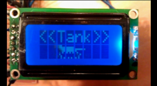
Step 8: See It Work!
The end result is a tank that moves across the screen.
One thing to note is that different LCD panels have different physical layouts and characteristics. On this board, there is a gutter line that is a pixel wide between each character, both vertically and horizontally. The display is 8 chars wide by 2 chars high. I experimented with different modulo settings, allowing character movement at every sixth shift, rather than every fifth, to compensate. That's something you have to play with, depending on what you're trying to draw. Another LCD panel I have came from an H-P printer, and it doesn't have the one pixel wide gutter separating the rows, but still has a gutter between each character.
The other thing is that to beware of is fade time and contrast. The potentiometer allows for different contrast settings, making it easier to see the pixels. The fade time can vary between panels. The longer the fade, the more delay you need, or else you'll run into blurry animation. Someone out there probably can find a way to take advantage of that fade, though. It seems to me there may be a clever way to generate "gray" levels by rapidly turning pixels on/off, but only if the timing is really accurate.
Finally, from a coding standpoint, this may well not be the most efficient way to do things. You could instead pre-render all the turrent bits, and all the tread bit combinations, and even pre-shift them to all the necessary locations. (Let's see, that'd be five combinations for the first four lines representing the turret, and three times five for the bit-shifted tread combinations, times eight long ints, for a total of 5x8 + 3x5x8 = 4x5x8 = 160 long ints = 640 bytes, pre-rendered. With different code, that may be cheaper than the space taken by the compiled code, and there are other middle ground solutions.
The actual code is on the last page of this Instructable.
Attachments

Step 9: Tank Code for 44780 / RT0802B-1 Ver 2.0
// This code is for a 44780 LCD 14-pin panel with 2 more pins for anode/cathode back lighting
#include <LiquidCrystal.h>
LiquidCrystal lcd(7, 8, 9, 10, 11, 12);
// RS, EN, DB4, DB5, DB6, DB7
// Board
// 1 = ground
// 2 = Vcc
// 3 = pot 10k-20k for contrast
// 4 = RS
// 5 = RW
// 6 = EN
// 11 = D4
// 12 = D5
// 13 = D6
// 14 = D7
// Search internet on 44780 for various pages that describe the wiring in great detail
// RW has to be wired low to write, else it remains in "read" mode
byte sprite0[8];
byte sprite1[8];
byte sprite2[8];
byte sprite3[8];
void setup() {
// set up the LCD's number of columns and rows:
lcd.begin(8, 2);
lcd.setCursor(0,0);
lcd.print("tankdemo");
lcd.setCursor(0,1);
lcd.print("@@@@@@@@");
memset(sprite0,7,8);
memset(sprite1,7,8);
memset(sprite2,7,8);
memset(sprite3,7,8);
lcd.setCursor(0,1);
// Serial.begin(9600);
}
// Need eight 32-bit quantities that I can use for shifting bits around.
// The original tank image is in these values.
long tankImg[] = {
((long)B010000 << 10) | ((long) B000000 << 5) | B000000 // antenna tip
,((long)B010111 << 10) | ((long) B011110 << 5) | B000000 // turret top
,((long)B001111 << 10) | ((long) B011111 << 5) | B011110 // turret mid with barrel
,((long)B000111 << 10) | ((long) B011110 << 5) | B000000 // turret base
,((long)B001111 << 10) | ((long) B011111 << 5) | B010000 // tread top
,((long)B010000 << 10) | ((long) B000000 << 5) | B001000
,((long)B010000 << 10) | ((long) B000000 << 5) | B001000
,((long)B001111 << 10) | ((long) B011111 << 5) | B010000 // tread bottom, 24 pixels total in tread
};
// tankx is the bitwise position across the screen.
// tankcharx is the character-wise position, thus tankx / 5.
// It can be negative.
// At tankx zero, the tank is on the left of the screen
// so tankImg bytes are broken into four custom chars
// the fourth of which being blank bits
// At tankx one, the tank bits shift a bit to the right
// and if I'm clever, the treads are computed so they "rotate"
// And so on
// Because there are five bits horizontally per custom char
// and the tank treads go every other, I can repeat the original
// tank treads starting at even char positions
int tankx = -15;
int tankcharx;
int tankchary = 1;
int treadx = 0;
#define BITS_PER_CHAR 6
void loop() {
tankcharx = tankx / BITS_PER_CHAR;
// Serial.print("tankx = ");
// Serial.print(tankx);
// Serial.print(" tankcharx = ");
// Serial.println(tankcharx);
// Initial rendition, no rotation of treads
if ((tankx % BITS_PER_CHAR) == 0) {
// Full shift is on, need to draw a blank where the tank last was
if (tankcharx >= 1) {
lcd.setCursor(tankcharx-1, tankchary);
lcd.write(' ');
}
if (tankcharx >= 0 && tankcharx <= 7) {
lcd.setCursor(tankcharx, tankchary);
lcd.write((byte)0);
}
if (tankcharx+1 >= 0 && tankcharx+1 <= 7) {
lcd.setCursor(tankcharx+1, tankchary);
lcd.write((byte)1);
}
if (tankcharx+2 >= 0 && tankcharx+2 <= 7) {
lcd.setCursor(tankcharx+2, tankchary);
lcd.write((byte)2);
}
if (tankcharx+3 >= 0 && tankcharx+3 <= 7) {
lcd.setCursor(tankcharx+3, tankchary);
lcd.write((byte)3);
}
}
// Compute the bits of the individual custom chars
int shiftbits = (tankx % BITS_PER_CHAR);
// Serial.print("shiftbits = ");
// Serial.println(shiftbits);
if (shiftbits < 0) { shiftbits += BITS_PER_CHAR; }
for (int y=0 ; y<8; y++)
{
long lval = tankImg[y];
switch (treadx) {
case 0:
switch (y) {
case 4:
lval ^= 0x2cb0; break;
case 7:
lval ^= 0x2490; break;
}
break;
case 1:
switch (y) {
case 4:
// lval ^= 0x1240; break;
lval ^= 0x36d0; break;
case 5:
lval ^= 0x0008; break;
case 6:
lval ^= 0x4000; break;
case 7:
lval ^= 0x0920; break;
}
break;
case 2:
switch (y) {
case 4:
// lval ^= 0x0920; break;
lval ^= 0x1b60; break;
case 5:
lval ^= 0x4000; break;
case 6:
lval ^= 0x0008; break;
case 7:
lval ^= 0x1240; break;
}
break;
}
long lshifted = lval << (BITS_PER_CHAR-shiftbits);
sprite0[y] = (byte)((lshifted >> (3*BITS_PER_CHAR)) & B011111);
sprite1[y] = (byte)((lshifted >> (2*BITS_PER_CHAR)) & B011111);
sprite2[y] = (byte)((lshifted >> (1*BITS_PER_CHAR)) & B011111);
sprite3[y] = (byte)((lshifted >> (0*BITS_PER_CHAR)) & B011111);
}
lcd.createChar(0, sprite0);
lcd.createChar(1, sprite1);
lcd.createChar(2, sprite2);
lcd.createChar(3, sprite3);
++tankx;
if (tankx >= 50) { tankx = -15; }
++treadx;
if (treadx == 3) { treadx = 0; }
delay(100);
}


