

Introduction: Arduino, Gyroscope and Processing


Hi guys, this is my first attempt to post a project here.
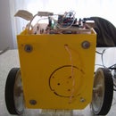
This is an instructable on how to read a gyro sensor and plot the data using processing software at your desktop. I am using gyroscope model XV81-000 and an arduino. The device is a rough prototype of what will eventually become a self balance robot, this is the first part of the hole thing (read accelerometer and control a motor to self balance).

Step 1: What You Need?
You will need:
- Breadboard
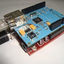
- Microcontroller, I used the Arduino board
- Wire
- Jumper Wires
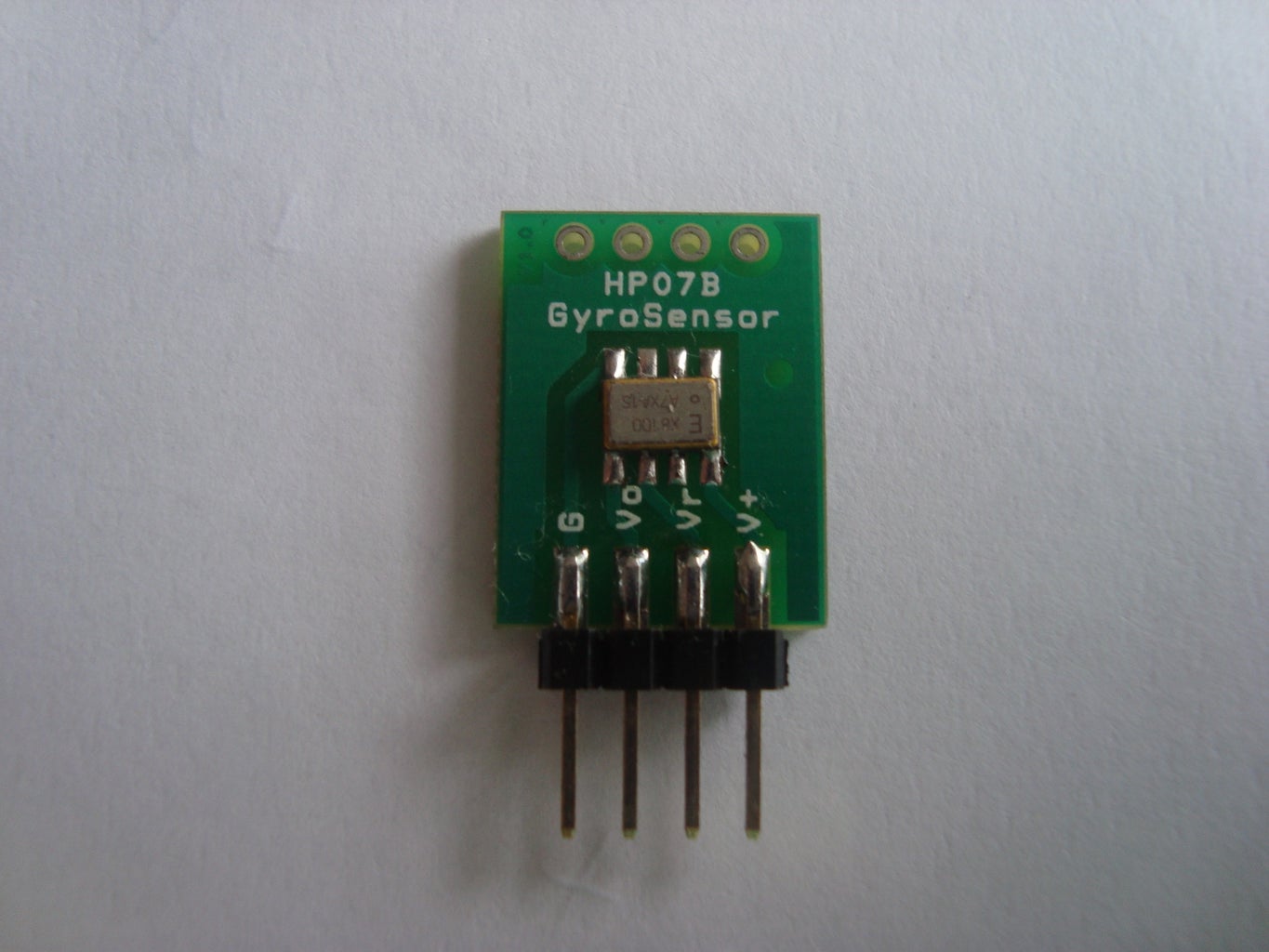
- Gyroscope XV-8100
Step 2: Building
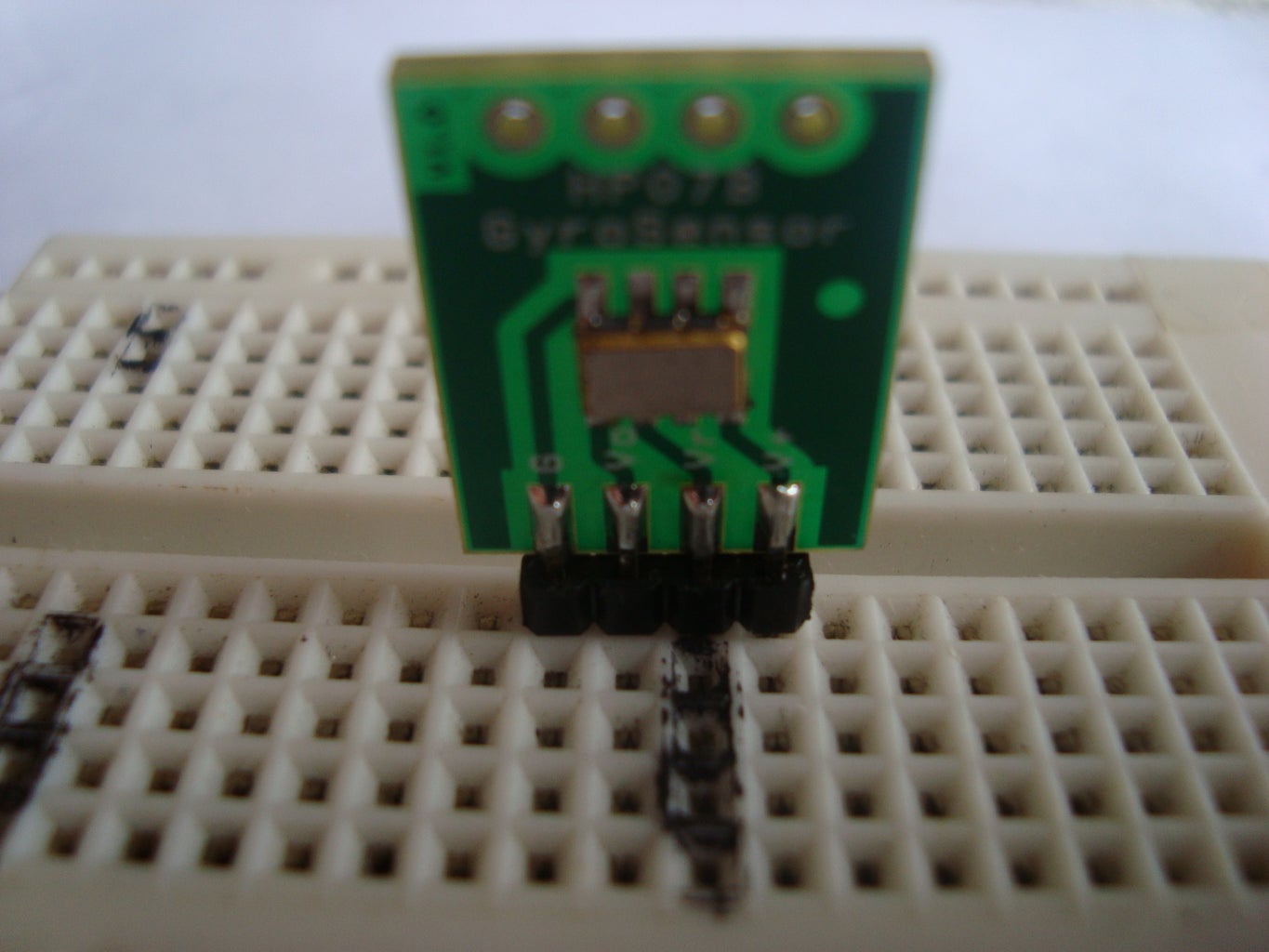


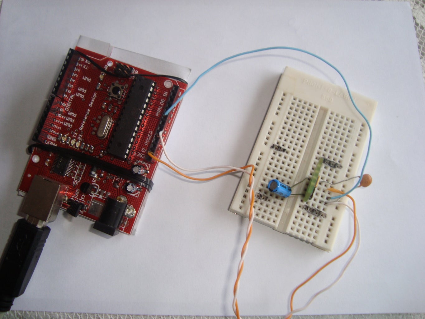
The circuit consists of a gyroscope connected direct to port 0 from your arduino. Some capacitor added to reduce noise from analog value.
1� - plug the gyro at the breadboard
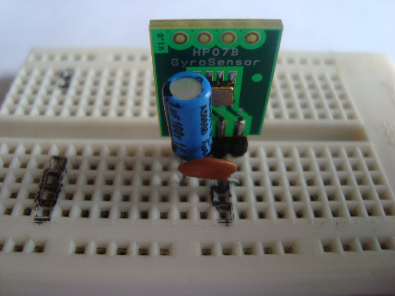
2� - plug a small ceramic capacitor to bypass the DC noise between the ground pin and the vout signal. (optional)
3� - add another capacitor to reduce even more the noise between the ground pin and the vcc pin. (optional)
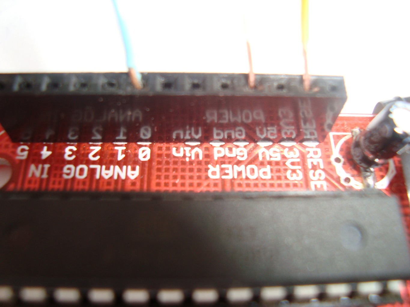
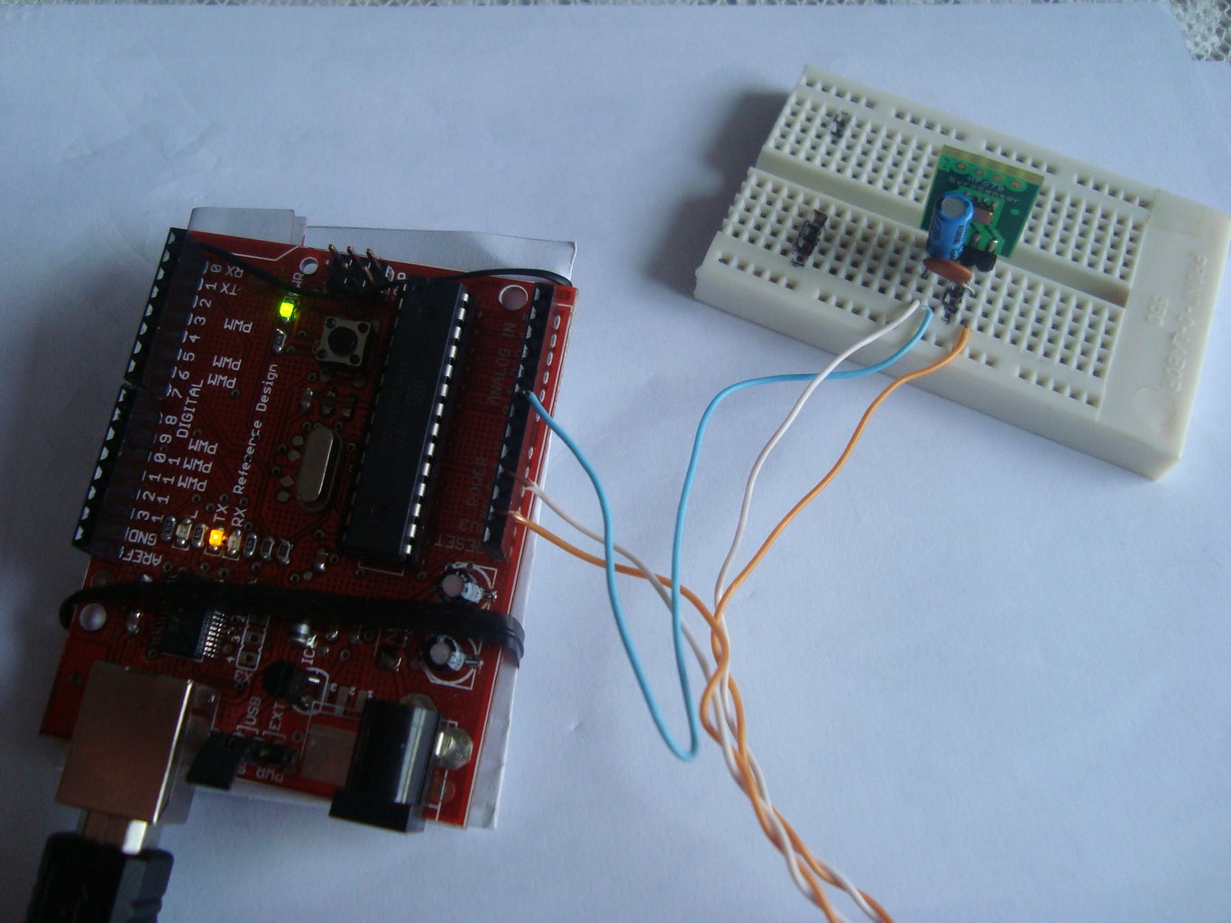
4� - wire ever thing:
- Vo pin from gyro connected to analog port0 at arduino (Blue wire)
- G pin from gyroconnected to ground (White wire)
- V+ pin from gyro connected to Vdd(3.3V) (Orange wire)
Step 3: Software


To communicate the arduino with the processing I used the standard firmata code, the same found inside the arduino's library. This library automatize the communicate process between the arduino and firmata. So is not necessary any modification at the arduino code. We will gone just edit the processing code according with our desire.
The processing code:
import processing.serial.*;
import cc.arduino.*;
Arduino arduino;
int ledPin = 13;
float value=0;
int first_try=1;
String stf="";
void setup()
{
size(400,400);
println(Arduino.list());
arduino = new Arduino(this, Arduino.list()[1]);
arduino.pinMode(ledPin, Arduino.OUTPUT);
frameRate(60);
delay(500);
}
float sens= 0.512;
float offset= 316 ;
float count= 0;
float valor =0;
float aux1=0,aux2=0;
int[] contador={
0,0,0};
float first_time, time;
float teta=0;
void draw() {
background(150);
fill(250,250,250);
arc(200,200,100,100,0,TWO_PI);
if(first_try==1){
//delay for arduino initialization
delay(2000);
first_try=0;
}
if (mousePressed == true) {
fill(255,0,0);
aux1=0;
aux2=0;
contador[0]=0;
contador[1]=0;
contador[2]=0;
teta=0;
arduino.digitalWrite(ledPin, Arduino.HIGH);
}
else {
fill(0,0,0);
arduino.digitalWrite(ledPin, Arduino.LOW);
}
//####################################################################//
// //
// Gyro //
// Scale Factor 2.5mV/ �/s = 0.512 counts/ �/s //
// Offset 316 counts = 1562mV = 1.562V //
// ADC 4.88 mV/count // 0.2048 count/mV //
// //
//####################################################################//
count =0;
for(int i=0;i<20;i++){
count = count + arduino.analogRead(0);
}
count = count /20;
valor = (count - offset ) / sens;
time=millis()-first_time;
first_time=millis();
teta=teta+valor*time/1000;
if(teta>-1 && teta<1) teta=0; //avoid drift error
PFont font;
font = loadFont("EngraversMT-48.vlw");
stf = str(teta);
textFont(font);
text(stf,150,270,200,200);
println("teta: "+teta+" count: "+count+" time: "+time+" valor: "+valor);
line(200,200,50*cos(radians(teta+270))+200,50*sin(radians(teta+270))+200);
}
Step 4: Turn On

Now that we have all we gonna need, lets uploaded the standard firmata code at arduino. The code is found inside the library folder of your arduino.
The processing code I posted at the previous page. The code initialize the firmata library read the analog port and plot it at your desktop .
The processing code need a little tune and I'm working on it. As soon i fix I will edit the code here. Feel free to edit and improve the code for a better performance, and let me know.
Turn on the arduino, compile the code and you gonna see a circle with a line at middle, wait a few seconds and click at the circle to reset the angle
When you turn the bread board, the line will turn to the same side.


