

Introduction: ArduinoPhone


Note that ArduinoPhone V2.0 had been published at Jan 26, 2016, click to view more details.
Combining Arduino and other shield modules, we make a mobile phone named Arduino Phone. Meanwhile, we printed a shell for it with the 3D printer. Although it’s not such fine as you think, even a little bit clunky, it’s still very cool. That is the point this is a cell phone made by ourselves.
While, we can’t install Arduino Phone Apps limited by Arduino. So, if you want to play Angry Birds, then you need to do some big modifications on Arduino Phone. :)
Next, I will make a detailed explanation about the steps of making an Arduino Phone, including the hardware connection and software implementation.
Now, let’s begin.
Step 1: Preparing Stuffs


At the very beginning, we’d better prepare the materials. Of course, most of these modules can be purchased directly, such as Arduino Uno, TFT Touch Shield and GPRS Shield.
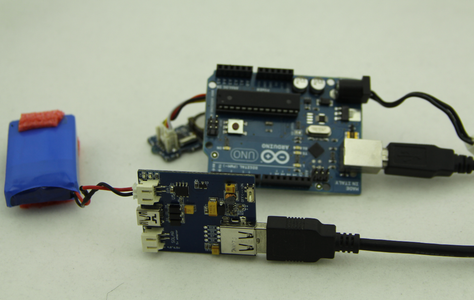
Owning to we want to put our Arduino Phone into a 3D printed shell, and in order to adapt the size of this shell, we have to DIY a charging and discharging PCB board (including two parts) and an expansion PCB board which can connect to the headphone jack of GPRS Shield.
If you want to make a shell by yourself, you can directly take Lipo Rider, or something like this, as the charge sheet. Thus, you do not need to DIY PCB board in order to meet the size of the shell.
What you need:
4.RTC
5.Custom ArduinoPhone Charge Circuit (or Lipo Rider)
7.A shell (with 3D printer)
All components at here.
Step 2: Hardware Connection


After preparing the materials, we need to assemble the above electronic components to lay the foundation functional part of Arduino Phone.
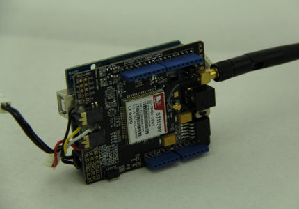
1.Plug GPRS Shield into Arduino UNI, then, connect the TFT Touch Shield to GPRS.
2.Connect RTC module to Arduino UNO.
2.Plug into the power module, and connect your earphone to the headphone jack on GPRS.
Well, if you choose to use Lipo Rider, you can refer to this sort of connection.
Ok, now, we are going to get into the software program part.
Step 3: Programming and Test


This Arduino Phone contains the following main functions.
1. receive & send message, letter input
2. dial & answer calls
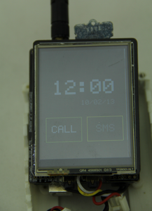
3. real time clock display
4. A convenient and concise UI, You can switch function by sliding your finger on the screen. A standard 12 key input method for inputting message.
You can get all of the Arduino Phone code from the Github, including the dependent libraries.
-------------------------Following was updated at Dec 7, 2015------------------------
1. When you get to the github page, find a Download ZIP button, click to download the code.
2. The code you downloaded is not an Arduino library, it's a sketchbook, which is include all the library the project need.
3. Unzip the file you had downloaded from github, you will get a folder named ArduinoPhone-master.
4. Open your Arduino IDE, click File > Preferences > Sketchbook Location, browse to the folder we had mentioned above - ArduinoPhone-master. Then click OK to save it.
5. Close and re-open Arduino IDE, click File > Sketchbook > PhoneCode, then the main code of Arduino Phone is open.
6. Choose the right board and port to upload the code.
Refer to the image above.
-------------------------Above was updated at Dec 7, 2015------------------------
However, a much more difficult problem is that this Arduino Phone hasn’t physical buttons
(except the Reset button switch and GPRS). So, how to manage UI will be a challenging task.
Fortunately, TFT Touch not only provides a display function, also a touch screen function.
Thus, we can manage the UI through gesture, like left-swipe and right-swipe.
It this step, we will show how ArduinoPhone works. And the picture indicates the workflow of ArduinoPhone.
Finally, opening ArduinoPhone.ino with Arduino IDE, then uplaod source code to ArduinoPhone.
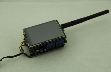
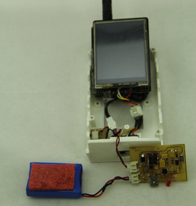
Step 4: Assembling


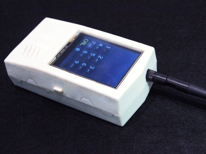

In order to make it look like a phone, we printed a shell with 3D printer as shown below. Then, assemble them carefully.
This is a troublesome but interesting process. Actually, maybe it will be more interesting if you put them into other shells, such as in shoes( see the picture :) ).
We are planning to do Arduino upgraded version. If you have any ideas or are willing to help us design a more perfect UI, welcome to contact me.
Step 5: Version 2.0


ArduinoPhone 2.0 had been published, which consists the below feature:
- Even more thinner, about 20 mm
- Support of solar and DC adopt charge
- Much more easy to install
- A longer standby time, more that 50 hours
- On board MIC and Speaker, say goodbye to the earphone
- 3D print sheel
Click ArduinoPhone 2.0 to get more info.
Cheers.

Second Prize in the
Arduino Contest


